
Views: 0 Author: Site Editor Publish Time: 2026-11-18 Origin: Site


Industrial fluid control systems demand continuous precision, stability, and reliable performance. When you hear a rapid, machine-gun-like hammering radiating from your piping network, you are likely experiencing valve chatter. This physical phenomenon involves the rapid, uncontrolled opening and closing of a valve disk against its seat. You must clearly distinguish operational valve chatter from minor mechanical background noise. Chatter represents a highly destructive oscillation caused by complex fluid dynamics and severe system pressure imbalances. Ignoring this intense vibration accelerates internal component failure, compromises process safety, and inevitably leads to costly unplanned downtime. Resolving this dangerous oscillation requires immediate engineering attention. Our objective is to provide you with a systematic diagnostic framework. We will guide you through isolating the root cause of chatter and evaluating structural corrective actions. You will learn how to transition seamlessly from system redesign strategies to specifying the exact replacement components your fluid application truly requires.
Primary Culprit: Oversizing is the most common cause of valve chatter, leading to insufficient flow to keep the valve fully open.
Systemic Risk: Prolonged chatter destroys valve internals, weakens piping joints, and can violate pressure safety compliance standards.
Diagnostic Approach: Resolving the issue requires evaluating inlet pressure drop, backpressure, and recalculating the exact flow coefficient (Cv) needed.
Material and Design Upgrades: Selecting the right valve architecture—such as specific configurations of a Globe Valve or a Stainless Steel Flanged Globe Valve—is critical for matching the valve's performance curve to the application's true operating conditions.
The internal mechanics of a fluid control system handle tremendous kinetic energy under high-pressure conditions. Rapid hammering damages the plug, seat, and stem almost immediately. The plug and seat are precision-engineered to maintain a tight seal. When rapid hammering occurs at frequencies of dozens of times per second, the kinetic energy shatters hardened facing materials. You will notice premature leakage as the sealing surfaces degrade. Repeated impacts deform the precision-machined angles inside the body. The stem often bends under the lateral forces generated by the severe vibration. Eventually, this mechanical degradation forces a complete structural failure, drastically shortening the expected lifespan of your equipment.
Vibration never stays isolated to a single component. Kinetic energy transfers rapidly through the connected piping system. This kinetic transfer causes significant fatigue in adjacent welds, pipe flanges, and structural supports. High-frequency oscillations induce intense cyclic stress. This cyclic stress initiates microscopic cracks in rigid joints. These micro-fractures grow over time and eventually compromise fluid containment. Facility engineers frequently discover compromised pipe hangers or broken brackets near a chattering unit. You must treat these system integrity risks seriously to avoid hazardous chemical spills or dangerous steam blowouts.
Pressure relief systems act as your primary safety net during emergencies. When a safety relief device chatters, it fails to reach its fully rated capacity. The rapid seating and unseating restrict the required escape volume drastically. This severe restriction risks catastrophic overpressure events in connected pressure vessels. Process plants must adhere strictly to ASME Section VIII and API 520 safety standards. Operating a chattering relief device directly violates these critical regulatory frameworks. It creates an unacceptable risk profile for facility personnel and local inspectors.
Financial burdens scale quickly when routine maintenance is deferred. You face extremely high emergency replacement costs when parts shatter unexpectedly. Unplanned shutdowns halt production lines, draining daily revenue streams rapidly. Facilities often spend heavily on expedited shipping for replacement parts just to restore operations. Maintenance crews must work expensive overtime hours to rebuild the piping networks. Fixing the root cause early prevents these massive financial losses. We highly advise against ignoring early warning signs of system instability.
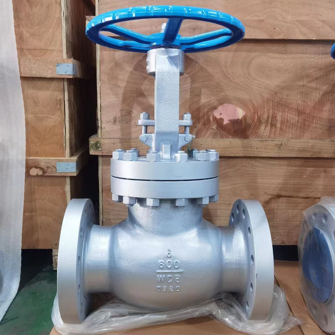
Engineers often specify piping components based purely on line size to simplify installation. This engineering reality causes widespread issues across industrial plants. A unit with too high a capacity for the normal flow rate will rapidly cycle. It struggles constantly to find a stable equilibrium position. The disk lifts slightly, passes the required flow, and immediately slams shut as pressure equalizes too quickly. This rapid, repetitive cycle creates the characteristic hammering noise. You must size components based on actual fluid flow calculations rather than matching pipeline diameters.
Inlet piping dimensions directly impact performance stability. Friction losses in long or undersized inlet piping starve the opening mechanism. When the unit opens, fluid accelerates and pressure at the inlet drops sharply. If the pressure falls below the operational set point, the disk reseats prematurely. As soon as it closes, static pressure rebuilds rapidly. The cycle repeats itself endlessly. Industry standards dictate you must keep inlet pressure drop below three percent of the set pressure to prevent this specific oscillation.
Exhaust piping dynamics heavily influence operational stability. Built-up or superimposed backpressure disrupts the delicate forces acting on the disk. High backpressure essentially pushes back against the internal opening mechanism. It alters the differential pressure required for stable operation. When the downstream pressure fluctuates violently, the disk flutters uncontrollably. Analyzing exhaust header capacities and downstream blockages remains a critical diagnostic step for any troubleshooting procedure.
Fluid turbulence ruins stable operation profiles. Installing devices too close to centrifugal pumps, sharp elbows, or flow-disturbing fittings invites disaster. The turbulent wake creates uneven pressure distributions across the internal sensing elements. Swirling fluids exert asymmetric forces on the internal stem, pushing it violently off-center. Manufacturers always recommend a minimum length of straight pipe upstream. Ignoring this installation rule guarantees operational instability.
Diagnostic Troubleshooting Chart
Observed Symptom | Likely Root Cause | Immediate Diagnostic Action |
|---|---|---|
Rapid machine-gun noise at low flow | Oversized capacity for current process | Calculate actual Cv requirements against datasheet |
Fluttering only during pump startup | Proximity to fluid turbulence | Inspect upstream straight pipe length dimensions |
Heavy vibration with upstream pressure drop | Inlet friction loss and starvation | Measure inlet pipe diameter and routing length |
Erratic popping on relief lines | Improper blowdown ring settings | Consult certified technician for recalibration |
Throttling applications require specific internal architectures to manage energy properly. We heavily prefer the Globe Valve for its exceptional flow control capabilities. Its linear motion design allows precise modulation. However, incorrect trim selection inherently leads to chatter in low-flow conditions. The fluid must navigate a tortuous Z-shaped path through the body. If the internal plug is oversized, it hovers too close to the seat. This extreme proximity creates high-velocity fluid jets that destabilize the plug. Choosing the correct characterized trim eliminates this instability completely.
Standard utility lines demand durability and massive construction. A properly sized Cast Steel Globe Valve provides the necessary structural rigidity. The heavy-duty casing helps dampen minor system vibrations effectively. Utility steam, cooling water, and basic compressed air lines benefit greatly from this robust construction. The sheer mass of the cast steel body resists external resonant frequencies naturally. It forms a highly solid baseline for reliable industrial flow regulation.
Extreme pressure differentials exacerbate chatter forces significantly. When pressure drops are severe across the seat, cavitation and flashing often occur simultaneously. You must specify a High Pressure Cast Steel Globe Valve to handle these destructive energies safely. These specialized units feature hardened trims, heavily guided plugs, and massive wall thicknesses. The rugged design withstands extreme fluid velocities without oscillating. They maintain absolute stability even when controlling highly energized steam or volatile hydrocarbons.
Chemical processing plants handle highly aggressive media daily. Internal pitting from corrosion alters flow dynamics unpredictably. Rough, degraded internal surfaces generate severe localized turbulence. We strongly recommend a transition to a Stainless Steel Globe Valve to prevent this degradation. The superior metallurgical properties resist corrosive attacks from harsh acids and bases. Smooth internal passageways ensure stable, predictable flow profiles over time, which naturally prevents chatter from developing.
Externally induced vibration worsens internal instability rapidly. Loose piping connections amplify any minor flutter into severe hammering. Specifying a Stainless Steel Flanged Globe Valve ensures rigid, leak-free integration into your piping system. Bolted flanges provide superior mechanical stiffness compared to standard threaded connections. This rigid mounting minimizes structural resonance across the entire piping network. A secure installation foundation fundamentally supports stable fluid control.
You must base your engineering solutions on hard data rather than assumptions. Begin by determining the accurate Flow Coefficient (Cv) based on actual operating data. Never rely solely on matching the existing line size. Collect accurate plant measurements of minimum, normal, and maximum flow rates. Calculate the required Cv for each distinct operating phase using standard ISA sizing equations. This mathematical precision ensures you select a unit capable of sustained equilibrium under actual plant conditions.
Sometimes the pipework itself creates the entire problem. You must address the implementation realities of reducing inlet pipe length immediately. Modifying industrial piping requires addressing several factors:
Eliminating unnecessary elbows or reducers right before the inlet.
Increasing the pipe diameter to minimize friction-induced pressure drops.
Ensuring adequate support structures limit external pipe movement.
Rerouting exhaust lines to lower system backpressure constraints.
Reworking industrial piping is often expensive and requires significant labor. However, it remains an absolutely necessary step when inlet starvation directly causes the oscillation.
Pressure relief devices require highly calibrated physical adjustments. You must carefully adjust the blowdown rings to achieve the correct reseating pressure. The upper ring controls the rapid pop action during an overpressure event. The lower ring dictates exactly when the unit reseats. Misaligned rings cause the device to flutter erratically during discharge. Only certified, trained technicians should perform these precise safety adjustments. Incorrect modifications can render a safety device entirely useless during an emergency.
Replacing an oversized unit requires a methodical approach. Follow this shortlisting framework when modifying pipework proves impossible:
Verify the actual system flow rates against the original design datasheet.
Identify reduced-trim options that fit seamlessly inside the existing body housing.
Calculate the new pressure drop profiles for the smaller internal trim.
Select a replacement unit with a performance curve exactly matching your lowest sustained flow.
Install the new equipment with rigid supports to eliminate sympathetic vibration entirely.
Valve chatter is always a visible symptom of a fundamental mismatch between system conditions and equipment specifications. You cannot ignore this destructive physical phenomenon without facing severe operational consequences. Sustainable fixes require rigorous, evidence-based sizing calculations and selecting appropriate metallurgical materials. Do not rely on applying temporary mechanical dampeners to mask the underlying problem. We strongly encourage facility managers and process engineers to audit all chattering devices thoroughly. Compare their current operational performance against the original process datasheets immediately. Always consult with qualified manufacturers to source properly right-sized replacements for your specific facility applications.
A: It typically presents as a rapid, machine-gun-like hammering or intense vibration, distinct from a steady hiss or high-pitched cavitation squeal. You will hear distinct metallic impacts. The sound often reverberates loudly through connected piping. It indicates a severe mechanical instability rather than normal fluid flow noise.
A: Sometimes. Modifying inlet piping, adjusting blowdown settings, or changing process flow rates can resolve it. However, if the unit is drastically oversized for the specific application, replacement remains the only reliable cure. Implementing reduced-trim internals can occasionally save the existing housing while fixing the flow profile.
A: Yes. Beyond destroying the internal mechanics, the resulting vibration causes catastrophic fatigue in piping connections. Furthermore, chatter restricts overall flow capacity. This prevents the system from safely handling overpressure events, posing severe risks to facility personnel and structural integrity.


