
Views: 0 Author: Site Editor Publish Time: 2026-11-01 Origin: Site


Industrial pipelines face a relentless operational challenge. Plant operators require robust shut-off mechanisms. These mechanisms must guarantee zero-leakage performance constantly. They operate in high-pressure, hazardous, or high-cycle environments. Refineries and chemical plants depend on them daily. Specifying the wrong valve carries severe operational consequences. It directly impacts your upfront capital expenditure. More importantly, incorrect selection jeopardizes overall plant safety. It drastically increases maintenance downtime. You need reliable flow control to prevent hazardous fugitive emissions. A failing valve puts personnel and the environment at serious risk.
This guide gives engineers and procurement teams a precise evaluation framework. You will learn to assess various structural designs thoroughly. We will explore specific material limits and boundaries. We will also cover essential regional compliance standards in detail. These insights ensure optimal system integration. Proper selection guarantees long-term mechanical reliability across your entire facility.
Flange end ball valves offer superior structural integrity and easier inline maintenance compared to threaded alternatives, making them standard for industrial pipework above 2 inches.
Selecting between floating and trunnion mounted designs depends strictly on the system's pressure class and pipe diameter.
Material choice dictates operational lifespan; while carbon steel is cost-effective for standard environments, corrosive media necessitates specific stainless steel grades.
Accurate specification requires matching flange dimensions to exact regional and pressure standards, such as ASME/ANSI or JIS10K.
A Flange End Ball Valve handles immense physical stress flawlessly. Flanged connections distribute this physical stress evenly across the pipeline interface. They are strictly necessary for larger pipe diameters. Engineers mandate them for high-pressure ratings. Threaded connections simply cannot handle these extreme operational environments. Threads act as stress concentrators under heavy mechanical loads. They pose a significant blowout risk during pressure surges. A flanged joint secures the pipeline mechanically. It prevents dangerous structural failures in hazardous chemical lines. Large pipelines experience substantial thermal expansion. Flanges accommodate this movement far better than threaded joints. They provide a rigid, leak-proof barrier.
Routine maintenance reveals the true operational advantage of flanged systems. You can remove the valve body entirely from the line. You do not have to cut pipe sections apart. You also avoid unthreading long runs of interconnected pipe. Mechanics simply unbolt the opposing flanges. They slide the valve out for immediate servicing. This plug-and-play capability significantly reduces downtime. It makes internal seat replacements fast and straightforward. Rapid inline maintenance keeps your plant running efficiently. Prolonged plant shutdowns cost thousands of dollars per hour. Flanged connections minimize this mechanical labor time. They allow technicians to swap units swiftly during planned outages.
Flanged systems carry some initial physical trade-offs. They possess a considerably larger installation footprint. They weigh significantly more than compact threaded alternatives. However, industrial settings demand uncompromising long-term reliability. Flanged connections meet strict corporate safety compliance rules. The added weight translates directly into structural robustness. They resist pump vibration and hydraulic shock better. Industrial operators gladly accept the larger physical footprint. The resulting safety and reliability far outweigh minor space constraints. Threaded valves often gall or seize over time. Flanged units simply require proper bolt lubrication for easy removal.
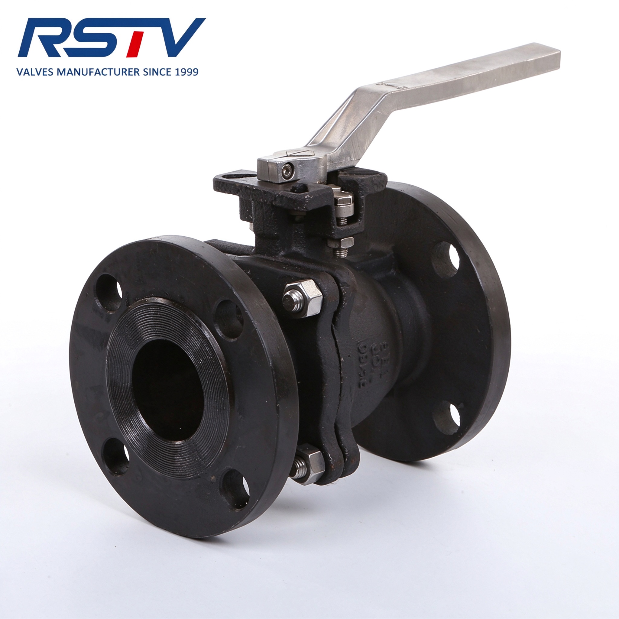
The floating ball mechanism relies heavily on internal pipeline pressure. Line fluid pushes the unanchored ball downstream mechanically. It forces the ball directly against the downstream soft seat. This mechanical action creates a tight, reliable seal. Engineers deploy these primarily in smaller piping diameters. They work best in pipes under four inches. You will find them frequently in low-to-medium pressure systems. The design features fewer internal moving parts. This simplicity makes them highly economical for utility lines.
However, the floating design has strict mechanical limitations. High-pressure applications push the ball too forcefully. This creates excessive operating torque requirements. It becomes physically difficult to turn the valve stem. The intense friction also causes accelerated downstream seat wear. The soft polymer seats degrade rapidly under heavy loads. You must avoid floating designs in severe high-pressure scenarios. They will leak prematurely if overstressed.
A Trunnion Mounted Ball Valve solves these critical high-pressure challenges. The internal ball anchors securely at the top and bottom. It does not float downstream under pressure. Instead, line pressure pushes spring-loaded seats directly against the stationary ball. This fundamental shift in mechanics protects the valve components. The seats move, rather than the heavy metal ball.
You should specify trunnion designs for high-pressure systems. They dominate Class 600 and above applications. They are also the strict standard for large diameter pipelines. The anchored ball design offers distinct engineering advantages. It dramatically lowers the required operating torque. Lower torque makes pneumatic automation highly cost-effective. Actuators require less air supply to cycle the valve. This improves the overall reliability of your automated control loops. Trunnion designs often include Double Block and Bleed capabilities. This enhances safety during pipeline maintenance.
Design Comparison Overview
Feature | Floating Ball Design | Trunnion Mounted Design |
|---|---|---|
Ball Movement | Pushed downstream by pressure | Anchored top and bottom |
Sealing Mechanism | Ball presses into downstream seat | Seats press into stationary ball |
Ideal Pipe Size | Under 4 inches | 4 inches and larger |
Pressure Rating | Class 150 to Class 300 typically | Class 600 and above |
Operating Torque | High (increases with pressure) | Significantly lower and stable |
A Carbon Steel Flange Ball Valve provides immense structural durability. These units excel in water, steam, and industrial oil applications. They handle non-corrosive gas flows effectively. Their primary strength lies in exceptionally high tensile strength. They resist mechanical shocks and sudden pressure spikes. Furthermore, carbon steel offers a lower procurement cost. It remains the industry standard for benign, non-corrosive environments. The WCB grade is highly prevalent in oil refineries.
Despite their physical strength, carbon steel valves have chemical vulnerabilities. They are highly susceptible to external environmental corrosion. Coastal or humid plants quickly degrade uncoated carbon steel. They also suffer internal degradation constantly. Acidic media will aggressively attack the internal metal walls. You must verify media neutrality before specifying this material. Abrasive particles can also erode unprotected carbon steel bodies.
When conditions turn harsh, you need upgraded metallurgy. A Stainless Steel Flange Ball Valve thrives in aggressive settings. We see them constantly in chemical processing facilities. Food and beverage plants mandate them for strict sanitation. Marine environments require them to combat harsh salt spray. They offer superior, inherent corrosion resistance. They also maintain structural strength across broad temperature extremes. The CF8M grade provides excellent resistance to localized pitting.
Stainless steel does carry a notably higher upfront cost. However, its extended lifecycle easily justifies this initial premium. Aggressive environments destroy lesser metals in mere months. Stainless steel survives for years without structural failure. It prevents disastrous chemical leaks and costly emergency replacements. Specifying stainless steel is an investment in plant longevity.
The valve body material alone cannot guarantee operational success. You must pair it with highly appropriate soft parts. Engineers select seats based on specific operating temperatures. They also closely account for the abrasive qualities of the media. Incorrect seals lead to rapid chemical degradation.
Consider these common industrial seat materials:
PTFE (Teflon): Delivers excellent chemical resistance for standard operating temperatures.
RTFE (Reinforced PTFE): Blended with glass fiber for significantly higher pressure tolerance.
PEEK: Withstands extreme high temperatures and highly abrasive fluid streams.
Metal-to-Metal: Essential for severe service, extreme heat, and heavy particulate flows.
A mismatch between internal seals and media causes rapid leakage. Always cross-reference your seal material against detailed chemical compatibility charts. Evaluate the primary fluid and any cleaning solvents used.
Flange dimensions follow strict, internationally recognized engineering protocols. Pressure classes dictate the exact physical geometry of the connection. Flange thickness increases dramatically as system pressure ratings rise. The bolt hole count also changes accordingly. A Class 150 flange looks vastly different from a Class 600 flange. Face-to-face dimensions expand to accommodate much thicker valve bodies. You must match the pressure class exactly during specification. Otherwise, the valve will physically not fit the pipeline gap. Attempting modifications in the field violates core safety codes.
Global piping infrastructure utilizes highly varied regional standards. The Americas primarily use ASME/ANSI technical specifications. Europe relies heavily on DIN metric standards. Asia leans heavily toward JIS engineering protocols. You must match the valve standard accurately to your site. Mismatched standards lead to severe mechanical misalignment. Misalignment guarantees immediate and dangerous fluid leakage.
Follow these essential dimensional matching steps:
Verify the existing pipeline flange standard.
Confirm the exact required pressure rating class.
Measure the required face-to-face clearance accurately.
Cross-reference the flange bolt circle diameter before purchasing.
Identify the flange face type.
Many specialized global applications demand specific regional geometries. A JIS10K Stainless Steel Ball Valve represents a common requirement here. Asian manufacturing sectors heavily specify the JIS standard. Maritime vessels and shipyards also utilize these dimensions frequently. The 10K designation indicates a typical pressure rating of approximately 10 bar. Specifying the exact JIS dimension is critical for seamless integration. Trying to bolt a JIS10K valve to an ANSI 150 flange will fail. The bolt circles simply do not align properly. You must procure the correct regional variant to prevent costly delays.
Improper installation destroys even the highest quality valves quickly. Flange alignment requires absolute mechanical precision. Mechanics sometimes use flange bolts to pull misaligned pipes together. This dangerous practice heavily warps the valve body. It permanently damages the sensitive internal seating surfaces. Uneven bolt torquing presents another major installation risk. You must use a staggered, crisscross star pattern. Uneven tightening crushes the flange gasket on one side. This mistake leads directly to immediate fugitive emissions. You must ensure adjacent piping is properly supported. The valve should never bear the physical structural weight of the pipeline. Use proper pipe hangers to relieve joint stress.
Many modern industrial facilities rely on automated process control. Adding pneumatic or electric actuators requires careful engineering calculations. You must calculate the correct safety factor for operating torque. Media characteristics change unpredictably over time. Sticky fluids or suspended solids drastically increase breakaway torque. A valve may stick if left in one position for months. We advise adding a 20% to 30% safety margin to actuator sizing. Undersized actuators will fail to close the valve during an emergency. This compromises the entire safety integrity loop of the plant. Always account for fluctuating air supply pressures.
Reactive maintenance causes highly disruptive and unnecessary plant shutdowns. We strongly recommend establishing a rigorous predictive maintenance schedule. Do not wait for visible external fluid leakage. Track the total mechanical cycle counts of each critical valve. Monitor the pipeline closely for unexpected pressure drops. Pressure anomalies often indicate internal seat passing. Schedule internal seat replacements during planned plant turnarounds. Regular acoustic emission testing can detect microscopic internal leaks early. Proactive servicing extends the overall lifespan of the flanged system. Keep spare seal kits readily available in your warehouse.
Selecting the proper industrial shut-off mechanism requires methodical analysis. You must match the connection type directly to your specific maintenance needs. Choose robust trunnion designs for high pressure and large pipe sizes. Stick to economical floating designs for smaller, standard applications. Always align your material choices with the media's exact corrosivity and temperature. Stainless steel protects against aggressive chemicals flawlessly. Meanwhile, carbon steel handles benign fluids with immense structural strength.
Your next step involves compiling a comprehensive specification sheet. Document exact pipe dimensions and precise media characteristics. Record maximum operating temperatures and all required compliance standards. Do this before requesting a formal manufacturer quote. Missing technical details inevitably lead to incorrect product recommendations.
We highly encourage consulting with a technical valve specialist immediately. They will verify your internal torque calculations expertly. They ensure vital face-to-face dimensional compatibility. Expert verification prevents costly installation delays and rework. Secure your pipeline infrastructure by finalizing procurement with accurate, expertly reviewed data. Taking these deliberate steps protects your facility completely.
A: Face-to-face dimensions are strictly governed by standards like ASME B16.10. They are not arbitrary. The length varies depending on the specific pressure class. It also depends on whether the valve features a short or long pattern design. You must consult the relevant standard tables to confirm the exact clearance required for your specific pipeline gap.
A: No, you cannot. Flange bolt circles, bolt hole diameters, and flange thicknesses differ drastically between pressure classes. They cannot be bolted together directly. Attempting to force them will cause severe leaks. You would need specialized spool pieces or transition flanges, which engineers generally do not recommend for safety reasons.
A: Early leaks usually stem from common installation errors. Incorrect gasket selection is a frequent culprit. Mechanics also cause leaks through uneven bolt tightening. You must always use a star pattern when torquing bolts. Attempting to use the flange bolts to forcefully pull misaligned pipes together will warp the assembly and ruin the seal.
A: You should upgrade to a trunnion design when operating torque becomes too high for standard automation. Upgrades are also necessary when dealing with pipe sizes above 4 to 6 inches. High-pressure gas or fluid lines, typically Class 600 and above, strictly require the anchored stability of a trunnion mounted ball valve.


