
Views: 0 Author: Site Editor Publish Time: 2026-09-23 Origin: Site


A high-performance valve is only as reliable as its connection to the pipeline. Selecting the wrong flange facing compromises seal integrity, leading to fugitive emissions, blown gaskets, or catastrophic flange failure. While engineers often focus heavily on valve materials and bore sizes, the mating face strictly dictates the mechanical limits of the joint. The flange face acts as the critical bridge connecting your piping infrastructure to your control mechanism. Overlooking this detail easily derails otherwise perfectly engineered systems.
This guide breaks down how to match flange facings to your specific pressure ratings, media, and piping systems to ensure leak-free operation. We will explore standard structural configurations, rigid material constraints, and precise alignment strategies. You will learn exactly how to prevent costly mismatches and specify the perfect joint for your next industrial pipeline installation.
The three most common flange facings—Raised Face (RF), Flat Face (FF), and Ring-Type Joint (RTJ)—are not interchangeable and must match the existing pipeline infrastructure.
Mating a Raised Face to a Flat Face (especially on brittle materials like cast iron) is a critical installation error that often results in flange cracking during torqueing.
Valve material dictates facing options: a stainless steel flange ball valve typically utilizes RF or RTJ, while cast iron variants are restricted to FF to prevent mechanical stress.
ASME B16.5 compliance should drive the final specification, aligning flange face, gasket type, and pressure class.
Leaks at the valve-to-pipe connection cause unplanned downtime. Environmental compliance violations quickly follow when pipelines vent hazardous media. Safety hazards rapidly emerge when extreme temperatures or corrosive chemicals escape the system boundary. A failing joint forces maintenance teams into dangerous emergency repair scenarios. Pipeline systems demand absolute containment.
The facing dictates how gasket compression behaves. Concentrating the bolt load onto a smaller physical area increases the direct pressure on the gasket. A smaller contact area, such as a Raised Face, ensures a tighter seal. High-pressure systems depend completely on this localized force to contain aggressive fluid dynamics. The correct facing prevents gasket extrusion under extreme system loads.
You need a stable, zero-leak seal. The chosen specification must easily match the anticipated lifecycle of the pipeline. It should eliminate any need for constant re-torquing during routine operations. A correctly specified flanged industrial ball valve holds strong under severe thermal cycling and unpredictable pressure spikes. Engineers evaluate success based on enduring mechanical stability rather than temporary fixes.
Common operational challenges to watch out for include:
Fugitive emissions triggered by improper surface finish specifications.
Gasket blowout caused by inadequate bolt load concentration.
Flange deformation due to incorrectly specified torque values.
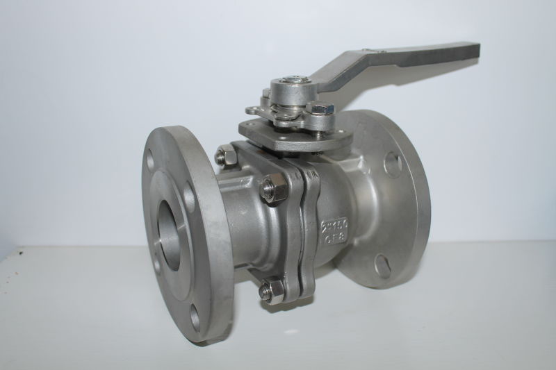
Piping systems utilize three primary mating surfaces. Each design serves distinct pressure classes and material combinations. Choosing the correct one determines the immediate success of the installation.
The surface immediately around the inner bore sits visibly higher than the surrounding bolting circle. This design physically concentrates the bolt load onto a smaller sealing area. It easily generates higher pressure against the installed gasket.
The Raised Face serves as the standard choice for most industrial plant piping systems. Engineers prefer it for carbon steel assemblies. It is highly common when installing a stainless steel flange ball valve. It handles moderate to high pressures beautifully while remaining easy to assemble in the field.
The entire mating surface remains completely flat. It sits flush with the outer bolting circle. This flat design requires a full-face gasket that covers the entire surface area. The wide contact zone prevents localized stress concentrations.
Flat Face flanges are mandatory for low-pressure applications utilizing brittle valve bodies. You will frequently see this on cast iron, bronze, or advanced plastic systems. The wide surface distributes structural stress evenly across the entire face. This prevents the delicate flange body from snapping under bolt tension.
This face features a precision-machined groove. It accepts a specialized metal ring gasket. As you tighten the bolts, the metal ring deforms slightly into the groove. This action creates a robust metal-to-metal seal.
RTJ designs thrive in extreme high-pressure and high-temperature environments. You will specify them for Class 600 applications and above. They provide unparalleled reliability when handling volatile hydrocarbons or superheated steam.
Primary Facing Features Comparison
Facing Type | Surface Characteristic | Primary Material Match | Ideal Pressure Range |
|---|---|---|---|
Raised Face (RF) | Elevated inner sealing area | Stainless Steel, Carbon Steel | Class 150 to Class 600 |
Flat Face (FF) | Flush across the bolt circle | Cast Iron, Bronze, Plastics | Class 125, Class 150 (Low Pressure) |
Ring-Type Joint (RTJ) | Machined metal groove | Forged Steel, High-Alloy Steel | Class 600 to Class 2500+ |
Selecting a valve involves more than matching the pipe size. You must carefully align the flange characteristics with the internal valve dynamics and material limits.
Forcing an RF connection onto an FF piping system creates a severe bending moment. Tightening the bolts pulls the unsupported outer flange edges toward each other. This immense bending force easily fractures brittle materials. Cast iron pipe flanges will crack audibly during installation if mated to a raised face steel valve. Always match flat to flat when dealing with brittle infrastructure.
Flow dynamics change rapidly at the connection point. When specifying a full port flange ball valve, the uninterrupted flow rate means higher potential turbulence. If the inner diameter of the gasket protrudes into the flow path, severe turbulence spikes immediately. Proper face and gasket alignment prevents flow disruption. Precise alignment also stops premature gasket degradation caused by high-velocity media abrasion.
Standard pressure classes dictate exact physical face dimensions. ASME B16.5 strictly governs these engineering tolerances. Class 150 and Class 300 connections standardize on a 1/16-inch raised face. Moving up the pressure scale changes the geometry. Class 400 and above mandate a 1/4-inch raised face. These precise measurements ensure dimensional compatibility across standard industrial infrastructure globally.
Field installations frequently expose critical specification errors. Understanding common failure modes prevents dangerous industrial accidents.
Contractors sometimes attempt to bolt a new RF flange end ball valve into an older FF cast-iron pipeline. This field reality causes immense mechanical stress. Inevitable failure follows as the brittle iron cracks under localized bolt load. Even if the flange survives initial torqueing, thermal expansion during operation will likely shatter the compromised joint. Never mix these facing profiles.
Do these valves have a specific flow orientation? Standard floating designs operate bi-directionally. You can install them facing either way. However, specialized models behave differently. Some feature a vented ball designed for cavity pressure relief. Others incorporate asymmetrical seating to handle aggressive chemicals. Installing these against the manufacturer's cast flow arrow causes premature seat failure. This catastrophic failure happens regardless of flange facing integrity.
The flange face represents only half the sealing equation. You must match the gasket perfectly to the face profile. Common mistakes include:
Using an RTJ gasket in an RF flange, which guarantees an immediate leak.
Placing a rigid spiral-wound gasket on an FF cast iron flange, which cracks the metal.
Applying incorrect torque sequences, resulting in uneven gasket compression.
Reusing old, permanently deformed gaskets on newly installed equipment.
Engineers follow a strict sequence to specify safe equipment. Follow these steps to ensure perfect mechanical compatibility.
You must actively match the new equipment to the mating pipeline flange. Identify the existing face type and the rated pressure class. Do not guess these parameters. Measure the outer diameter, the bolt circle, and the number of bolt holes. Document the precise face profile currently welded to the pipe.
Use the specific pressure and temperature (P/T) profile of your media. Dictate if an RTJ or standard RF configuration is required. Steam applications often mandate RTJ above certain temperatures. Standard chilled water systems operate perfectly fine using standard RF profiles. Let the extreme upper limits of your system dictate the specification.
Ensure the required flange face is fully compatible with the desired body material. Choose RF for stainless or carbon steel applications. Restrict your choice to FF when dealing with cast iron or PVC piping. Selecting a Flange End Ball Valve cast in brittle metal limits your facing options strictly to flat profiles.
Check all dimensional data against ASME B16.5 for steel components. Consult ASME B16.1 when specifying cast iron components. Ensure exact dimensional compatibility before finalizing the procurement order. Request the manufacturer's technical drawings to verify flange thickness and raised face height. Adhering to recognized standards guarantees safe, predictable field performance.
Choosing the right flange facing is not a simple user preference. It stands as a rigid engineering requirement dictated entirely by the mating pipe, system pressure, and body material. You must align these three factors perfectly to prevent catastrophic pipeline leaks. A minor mismatch in facing types easily translates into major environmental hazards or unplanned facility shutdowns.
Advise your procurement and engineering teams to extensively document existing pipeline flange specifications before requesting a quote. Never assume the pressure class or facing style based merely on pipeline diameter. Prompt your technical teams to consult directly with a verified valve manufacturer. Verify all ASME compliance data for your specific application to ensure a seamless, leak-free installation.
A: It is highly discouraged and often dangerous. Doing so creates a gap outside the raised face. When bolts are tightened, it creates a bending force that can easily crack brittle FF flanges (like cast iron) or warp the connection, leading to leaks.
A: Standard flanged ball valves are bi-directional. However, valves with unidirectional seals, vented balls for cryogenic/chlorine service, or specific trunnion designs must be installed according to the flow arrow cast on the body.
A: Under ASME B16.5, Class 150 and Class 300 flanges have a standard 1/16-inch (1.6 mm) raised face. Class 400 and higher utilize a 1/4-inch (6.4 mm) raised face.


