
Views: 0 Author: Site Editor Publish Time: 2026-10-22 Origin: Site


In complex fluid handling systems, selecting the wrong multi-port valve configuration invites disaster. You risk cross-contamination, deadheading, or complete system failure. Plant engineers and procurement teams face a persistent challenge during system design. They struggle to definitively choose between L-port and T-port configurations. This confusion often risks inefficient piping layouts and costly rework. Proper selection demands a clear understanding of internal mechanical routing.
Understanding precise flow routing simplifies your overall system architecture. An L port three way ball valve reliably diverts or isolates media using a single component. Navigating these choices requires careful attention to internal ball geometry. We break down these exact flow patterns below. You will see how they contrast directly against mixing alternatives. We also outline the technical criteria necessary for confident procurement decisions. Exploring these mechanics empowers you to specify piping components safely and correctly.
Internal geometry dictates the flow path entirely. Manufacturers machine the valve bore at a precise 90-degree angle. This L-shaped cavity inherently prevents straight-through fluid movement. The design forces media to turn inside the valve body. Engineers classify this specific geometry as a diverter configuration. It serves one primary purpose in piping networks. It connects a common central port to one of two side branches.
Let us examine the primary operating state. Fluid enters through the bottom entry point. This entry serves as the common inlet port. The internal angled bore directs this fluid outward through the right port. The left port remains completely sealed. PTFE seats block any fluid from bypassing the ball. The system maintains full pressure directed toward a single designated pipeline.
Actuating the valve 90 degrees changes the flow state completely. The internal ball rotates its L-shaped cavity. Fluid still enters through the bottom common port. However, it now exits exclusively through the left port. The right port becomes completely sealed off. This simple quarter-turn action achieves instantaneous source switching. Operators can redirect flow quickly without stopping system pumps.
You can isolate the entire pipeline using this same component. Many manufacturers provide a specific handle and stop-plate configuration. Turning the valve 180 degrees rotates the solid side of the ball toward the common port. This action blocks all three ports simultaneously. It provides a complete system isolate. Maintenance teams rely on this feature to secure process lines during equipment servicing. Always verify this capability, as not every L-port model includes a 180-degree stop.
You must account for transition dynamics during actuation. A momentary flow restriction occurs while the ball turns. Engineers call this brief period "overlap." The ball cavity temporarily seals the common port before opening the adjacent port. You must evaluate system pressure tolerance during this split-second transition. Momentary pressure spikes can stress sensitive upstream components. Careful evaluation ensures pipeline safety during automated switching.
Note: Always verify the manufacturer's specific flow plan document prior to installation. Assuming standard port designations across different brands often leads to critical piping misalignments.
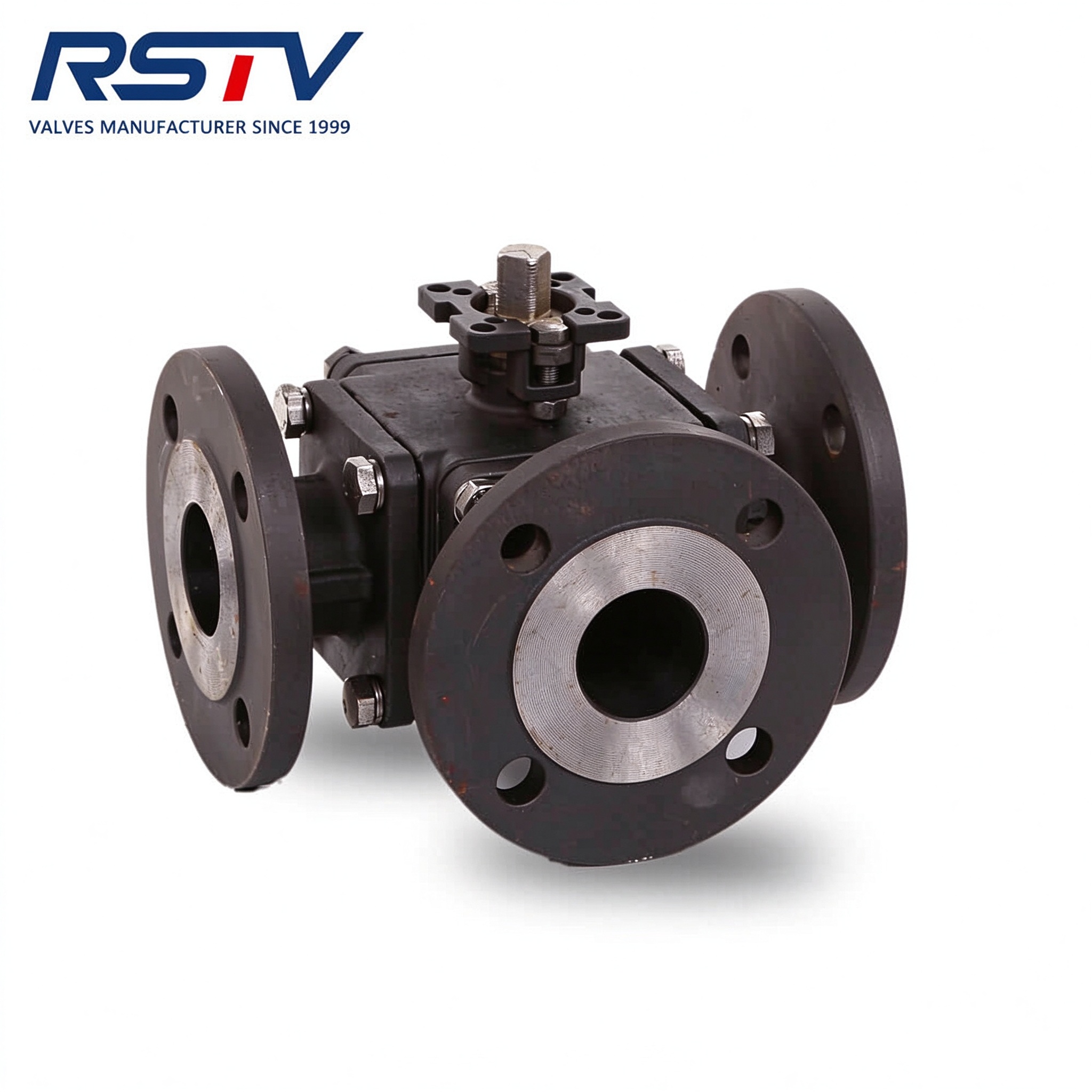
A durable three-way ball valve designed to handle high-pressure flow diversion securely.
Selecting multi-port valves requires a simple initial assessment. You must determine the fundamental process requirement. The choice ultimately boils down to "Diverting" versus "Mixing or Splitting." An L-port configuration excels strictly at diverting flow. It acts as a mechanical switch for fluid systems. Understanding your exact process requirement eliminates procurement guesswork early in the design phase.
You must contrast diverters against mixing components. A T port three way ball valve features a different internal layout. Manufacturers machine a straight-through bore containing a perpendicular branch. This unique T-shape enables complex fluid routing. It allows for fluid mixing from two independent sources. It can also split one source into two separate lines. Furthermore, it permits straight-through flow while isolating the third branch.
L-port geometries offer specific reliability advantages. They enable rapid source-switching without any risk of cross-contamination. You cannot accidentally mix two distinct chemicals. L-ports also offer much simpler automation logic. They present fewer viable flow combinations for controllers to manage. This simplicity reduces programming errors during system commissioning. Plant operators appreciate the straightforward "either/or" directional control.
Use the structured comparison below to guide your specification process. It highlights the functional boundaries of each configuration.
| Feature Assessment | L-Port Valve | T-Port Valve |
|---|---|---|
| Primary System Function | Strictly diverting flow (alternating sources) | Mixing, splitting, or straight-through flow |
| Media Mixing Capability | No (Prevents cross-contamination) | Yes (Blends two distinct fluid sources) |
| Handle Rotation Needs | 90° for diversion; 180° for shut-off | 90° to 180° depending on flow plan |
| Automation Logic Complexity | Low (Simple binary state switching) | High (Requires managing multiple open states) |
Tip: If your application requires media from two tanks to blend simultaneously into a single line, eliminate L-port options immediately and specify a T-port valve.
Industrial facilities frequently deploy redundant pumping architectures. Engineers use L-ports to alternate flow between a primary and backup pump. You can seamlessly route fluid toward the active equipment. This configuration reduces downtime during critical maintenance cycles. It eliminates the need for a complex network of standard two-way valves. Operators simply throw a single lever to engage the standby pump.
Filtration arrays require regular element replacements. L-ports excel at managing these maintenance bypass loops. They direct fluid through a primary filtration system during normal operations. When filter elements clog, operators actuate the valve. The system instantly diverts flow to a secondary standby loop. This routing ensures continuous process flow. The primary housing safely depressurizes for manual cleaning.
Chemical dosing processes rely heavily on precise source selection. A single process line must often draw from separate storage vessels. Operators use these valves to select either Tank A or Tank B securely. The internal geometry guarantees zero crossover between the two tanks. This strict separation prevents dangerous chemical reactions. It also ensures accurate batch formulation during production runs.
Modern plant design prioritizes efficient component usage. Replacing two or three standard 2-way isolation components simplifies the layout. A single Three Way Ball Valve accomplishes the same directional control. This consolidation reduces potential leak paths dramatically. It minimizes the physical installation footprint inside cramped skids. Ultimately, using fewer components lowers overall procurement and installation costs.
Note: Using a single multi-port valve instead of a manifold of two-way valves reduces flange connections by up to 30%. This consolidation measurably decreases fugitive emission risks.
Body material selection directly impacts your lifecycle return on investment. Standard brass or PVC bodies work adequately for basic water transport. However, severe industrial environments demand robust metallurgy. Specifying a carbon steel three way ball valve provides superior structural integrity. Carbon steel withstands high-temperature and high-pressure conditions effectively. It performs exceptionally well in harsh petrochemical applications. Careful material matching prevents premature body fatigue and eventual pressure boundary failure.
Transitioning from manual handles to automated control requires specific engineering steps. Pneumatic and electric actuators replace human intervention. You must follow strict guidelines when pairing these components.
Multi-port components exhibit distinct mechanical resistance profiles. Three-way valves inherently require higher operating torque than standard inline models. This increased resistance stems from the friction of additional seating surfaces. The internal ball rubs against three or four separate PTFE seats. You must size automated actuators carefully. Engineers apply an appropriate safety factor during sizing calculations. Typical safety margins range between 20% and 30% above the published breakaway torque.
Tip: When automating an L-port valve, ensure your PLC programming accounts for the specific cycle time of the actuator. This timing prevents brief pressure spikes in sensitive piping networks.
Orientation matters significantly during pipeline integration. You must clarify how the entry point affects flow capacity. Engineers measure this capacity using the Flow Coefficient (Cv) value. Bottom-entry configurations often yield distinct fluid dynamics. They produce different pressure drops compared to side-entry configurations. Fluid entering the bottom experiences a uniform 90-degree turn in either direction. Side entry forces fluid straight across or turns it abruptly. Always review performance curves based on your intended flow path.
Improper valve sequencing poses severe equipment risks. Deadheading occurs when pumps push fluid against a completely closed barrier. If a pump continues running while the L-port is mid-turn, pressure spikes rapidly. Similar risks arise if the actuator stalls in a shut-off position. This trapped energy damages pump seals and fractures pipe joints. You must interlock pump motor controls alongside valve limit switches. This electrical integration prevents disastrous mechanical failures.
You must understand how internal pressure affects seating surfaces. The closed port still endures full process line pressure. The fluid pushes the floating ball slightly downstream against the opposite seat. Uneven wear on PTFE seats occurs frequently. This degradation accelerates if operators leave the valve in partial-turn positions. Always actuate the component fully into its intended locking detent. Partial states expose seat edges to abrasive media erosion.
Physical orientation indicators prevent costly human errors. Manual overrides happen during power outages or system maintenance. Field technicians need immediate visual confirmation of the flow path. Emphasize the necessity of physical directional arrows on the handle. Actuator shafts should feature clear T-notches or L-notches. These markings ensure safe manual operation when control screens go dark.
Note: Always calculate your required Flow Coefficient (Cv) based on the specific angled flow path. An L-port will naturally generate a higher pressure drop than a straight-through two-way valve of the same diameter.
An L-port multi-way valve serves as an invaluable tool for process control. It safely diverts fluid and isolates process lines reliably. It performs these tasks efficiently provided the internal flow logic matches your facility needs. Selecting the right configuration eliminates complex manifolds and reduces fugitive emissions.
You must map out exact process requirements early. Distinguish clearly between mixing and diverting tasks. Verify your acceptable pressure drops using accurate Cv calculations. Always select durable body materials like carbon steel to ensure true industrial longevity. Avoid under-sizing automated actuators to overcome multi-seat friction.
We encourage you to consult technical sales engineers before finalizing piping designs. Utilize online valve configuration tools to match exact port geometries with appropriate fail-safe actuators. Accurate specification guarantees seamless integration and long-term fluid handling success.
A: No. L-port valves are strictly designed for diverting flow. The internal 90-degree bore prevents two incoming streams from blending. To mix fluids, a T-port configuration is required.
A: Yes, depending on the handle and stop configuration. Turning the L-port 180 degrees rotates the solid side of the ball toward the inlet. This action blocks all three ports.
A: No. The internal machining of the ball is fundamentally different. You cannot reconfigure the flow path externally. You must replace the ball or the entire valve assembly.
A: Not necessarily. The 90-degree turn inherent in an L-port design introduces fluid friction. This results in a specific pressure drop (Cv) that you should verify on the manufacturer's data sheet.


