Views: 0 Author: Site Editor Publish Time: 2026-06-12 Origin: Site


Regulating fluid flow safely remains a core engineering challenge across modern infrastructure. Doing it without destroying the pipeline infrastructure demands immense precision. Industrial operators constantly face pressure to keep complex systems running smoothly under extreme physical conditions. Unfortunately, many facilities experience devastating equipment failure rates during standard operations. Operators often mistakenly use standard on/off isolation valves, like gate valves, for partial-flow regulation. Forcing these simple valves to restrict fluid intentionally causes rapid internal erosion and dangerous mechanical wear. You need specialized equipment designed specifically for this rigorous task. In this guide, we will explore why specific internal geometry makes the globe valve for throttling the absolute industry standard. You will discover how these mechanisms ensure precise, repeatable flow regulation in unforgiving high-pressure environments.
The perpendicular movement of a globe valve’s disc relative to the seat allows for proportional flow control without the rapid wear seen in gate or standard ball valves.
While they inherently create a higher pressure drop (ΔP), this is a calculated tradeoff for superior cavitation resistance and precise flow modulation.
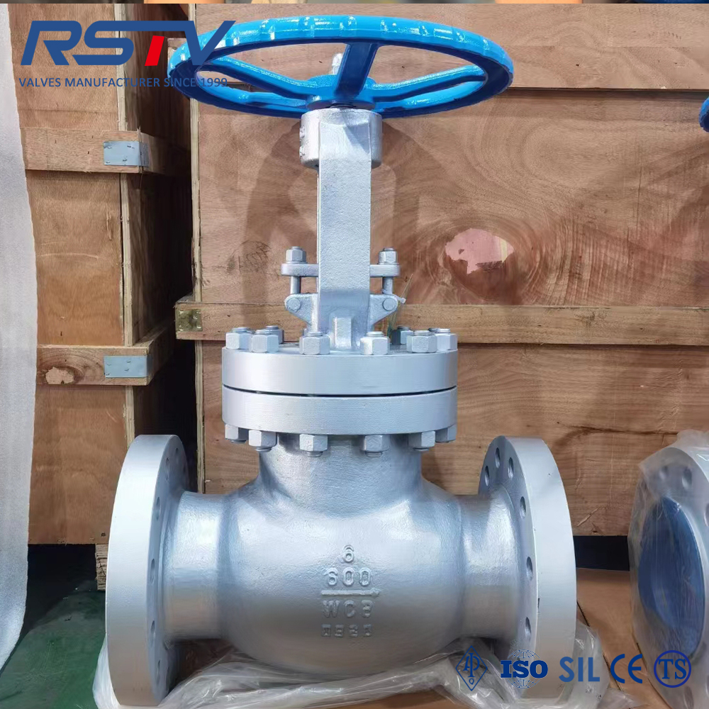
Material selection, particularly specifying a cast steel globe valve, is critical for high-temperature and high-pressure industrial throttling applications.
Choosing between standard T-pattern and Y-pattern globe valves depends strictly on the acceptable flow resistance and installation footprint of the specific system.
Forcing fluid through a partially closed aperture alters its physical state entirely. As the opening narrows, the fluid velocity spikes dramatically. Simultaneously, the pressure drops steeply across the restriction point. This sudden change creates intense kinetic turbulence inside the piping. Fluid no longer flows in a smooth, laminar fashion. It crashes violently against internal boundaries.
Improper valve geometry cannot handle these physical extremes. When liquid pressure falls below its vapor pressure, bubbles form rapidly. They then violently collapse against the metal surfaces. This phenomenon is known as cavitation. It accelerates seat erosion and pitting at an alarming rate. Over time, cavitation causes catastrophic trim failure. If the fluid remains a vapor after the pressure drop, flashing occurs. Both cavitation and flashing quickly destroy internal metal surfaces if the equipment lacks the proper design to absorb the energy.
Misapplying equipment introduces massive operational risks to your facility. Using a standard isolation valve for regulation guarantees frequent replacements. It causes unpredictable, unplanned downtime across the entire plant. Furthermore, compromised system safety puts workers and local environments in grave danger. A reliable industrial globe valve eliminates these operational headaches. It handles the brutal physics of partial flow without suffering premature mechanical death.
The internal design of this equipment inherently manages kinetic energy. The valve body features internal baffling. This forces the fluid to change direction twice as it passes through. This S-shaped flow path creates a controlled, calculated resistance. It allows the internal disc to modulate flow smoothly across various positions. The complex geometry dissipates destructive turbulence safely before it damages the delicate seating surfaces.
Mechanically, linear motion outperforms rotary motion for flow regulation. Quarter-turn mechanisms rotate on an axis to open. Their internal flow area increases non-linearly, making it hard to tune. In contrast, linear motion provides exact, mathematical control. The plug-type seating moves straight up and down along the stem axis. This vertical travel creates a highly predictable Flow Coefficient (Cv) curve. Operators can dial in exact flow rates easily. They know exactly how much fluid passes at ten percent versus fifty percent open.
Engineers specify different plug shapes to handle unique operational challenges. These trim variations make a flow control globe valve highly adaptable. You can perfectly match the flow characteristics to your specific system demands.
Trim Variations and Flow Characteristics Chart | ||
Plug Shape / Trim Type | Flow Characteristic | Best Application Scenario |
|---|---|---|
Quick Opening Plug | Maximum flow achieved early in travel | Systems needing fast, large volume delivery |
Linear (V-Port) Plug | Flow directly proportional to travel | Liquid level control and general regulation |
Equal Percentage (Parabolic) | Flow changes by equal percentages | Systems with widely varying pressure drops |
Gate valves exist strictly for on and off isolation. Attempting to throttle with them creates disastrous operational results. High-velocity media aggressively hits the partially lowered wedge. This physical impact causes severe disc vibration inside the pipeline. The high-speed fluid pulls metal away from the seating surfaces, a process known as wire drawing. Eventually, galling occurs between the moving parts, locking the valve completely. Conversely, globe valves fully support continuous partial opening. They operate smoothly without suffering any structural degradation.
Standard ball valves also lack the required geometry for fine modulation. Their internal flow area changes drastically when you turn the handle slightly. This non-linear shift makes precise control nearly impossible. Furthermore, the internal seals easily suffer from blowout under high differential pressure. Fluid slips past the ball and destroys the soft polymer seats. A dedicated throttling globe valve offers exact micro-adjustments. It safely handles extreme pressure differentials without risking catastrophic seat blowout.
Feature | Gate Valve | Standard Ball Valve | Globe Valve |
|---|---|---|---|
Primary Function | Isolation (On/Off) | Isolation (On/Off) | Regulation & Isolation |
Throttling Capability | Poor (Causes damage) | Poor (Non-linear flow) | Excellent (Precise control) |
Cavitation Resistance | Very Low | Low | High |
Wear Resistance | Prone to wire drawing | Prone to seat blowout | Highly resilient geometry |
Lighter materials fail quickly under severe conditions. You must evaluate your media before installation. You should often specify a cast steel globe valve for demanding applications. Cast steel excels particularly in high-temperature steam lines. Petrochemical plants rely heavily on it for strict API 600 compliance. It provides the necessary tensile strength to withstand thermal shock and high pressure. Cheaper alloys simply warp or crack under similar stress.
Body pattern configurations dictate how the unit physically fits into your pipeline. You have three primary choices to evaluate based on your system dynamics:
T-Pattern (Standard): This is the most common shape. It works best for severe throttling where pressure drop is acceptable or strategically desired. The fluid makes a severe Z-shape or S-shape turn.
Y-Pattern: This represents the smart compromise choice. It offers excellent throttling capabilities but angles the stem at approximately 45 degrees. The straighter flow path minimizes unwanted pressure drop.
Angle Pattern: This design is perfect for piping setups requiring a 90-degree turn. It handles the regulation duty while eliminating the need for an extra pipe elbow.
Seat and disc metallurgy determine the ultimate lifespan of your equipment. Abrasive media destroys standard internal metals rapidly. High-velocity fluids demand extensive hardfacing treatments. Stellite overlays significantly mitigate erosion. These hardened alloy surfaces keep the plug and seat intact. They ensure tight shutoff even over decades of continuous modulation.
You must address the primary downside of this technology transparently. The intricate S-shaped path creates inherent flow resistance. It results in a higher pressure drop (ΔP) across the valve body. You must accurately calculate whether your system pumps can handle this friction. You should never install this equipment without verifying your pump capacity. It remains a necessary tradeoff. You accept the pressure drop to gain superior cavitation resistance and precise control.
Actuation torque requirements differ significantly from rotary devices. Fluid pressure acts directly against the large surface area of the internal disc. Pushing the plug down into the flowing stream requires substantial physical force. This physical reality requires much larger actuators. Heavy-duty gearing mechanisms are necessary to open and close the unit. You cannot rely on simple hand levers for high-pressure systems.
Installation orientation matters immensely for system stability. You must orient the flow direction correctly. Install the unit for "flow under the seat" (flow-to-open) when dynamic stability is your priority. The media pushes against the bottom of the plug, preventing it from slamming shut unexpectedly. Conversely, install it for "flow over the seat" (flow-to-close) when tight shutoff is the absolute priority. The downstream media pressure helps push the disc down, sealing the valve tightly against the seat.
Selecting the right equipment requires a methodical approach. Do not guess the specifications based on pipe size alone. Follow this framework to ensure you purchase the correct unit for your facility.
Define system parameters: Map the exact operating temperature first. Calculate the maximum pressure differential your system will experience. Determine the required Cv range to ensure the valve matches your specific fluid dynamics. Over-sizing or under-sizing destroys operational efficiency.
Match the pattern to the pipeline: Determine if your piping system can easily absorb a standard T-pattern pressure drop. Assess if a Y-pattern is mandatory for hydraulic efficiency. Look at the physical space constraints to see if an angle pattern solves a piping layout issue.
Vendor evaluation criteria: Look strictly for manufacturers providing certified flow curves for their products. Demand strict API and ASME compliance documentation upfront. Always request traceable material test reports (MTRs) for any cast steel components. This guarantees the metallurgical integrity of your purchase.
Globe valves represent a higher initial structural investment for industrial facilities. They undeniably require careful hydraulic planning regarding their inherent pressure drop. However, they remain the only reliable mechanical solution for continuous, precise flow regulation. They protect your pipeline infrastructure from cavitation, flashing, and severe kinetic wear. Using the right material and internal geometry guarantees long-term operational success.
Never leave your system safety to chance. Review your current flow control requirements and map your required pressure differentials. Consult with a qualified valve sizing engineer today to review your system parameters. Download a technical spec sheet from a certified manufacturer to ensure your next installation meets all API and ASME standards.
A: No, a standard ball valve is designed primarily for on/off isolation. Its rotary design makes the internal flow area change non-linearly, preventing precise control. The high fluid velocity can also blow out the soft internal seats. Specialized V-port ball valves can throttle, but they still struggle with the extreme cavitation resistance that a globe valve naturally provides.
A: The pressure drop is higher because of the internal S-shaped flow path. Fluid must change direction twice as it passes through the internal baffling. This necessary redirection creates internal friction and flow resistance. While it causes a measurable pressure drop, it effectively dissipates destructive kinetic energy for smooth regulation.
A: You should choose a Y-pattern when you need solid throttling capabilities but cannot afford a severe pressure drop. The Y-pattern features a straighter fluid path, significantly reducing internal flow resistance. It is the ideal choice for continuous regulation in systems where hydraulic pumping efficiency is highly critical.
A: The best direction depends on your primary operational goal. "Flow-to-open" (media flowing under the seat) is best for general throttling because it offers dynamic stability and prevents the plug from slamming shut. "Flow-to-close" (media flowing over the seat) is preferred when achieving a tight, absolute shutoff is your main priority.


