Views: 0 Author: Site Editor Publish Time: 2026-06-18 Origin: Site


Industrial pipeline leaks often start subtly. Even minor seepage compromises site safety protocols. It wastes valuable resources and creates immediate compliance risks. Securing an absolutely tight seal feels impossible without sufficient line pressure.
In low-pressure pipeline systems, achieving a reliable, bubble-tight seal is notoriously difficult. Insufficient line pressure fails to force the valve mechanism fully closed. System engineers frequently over-specify valves. This cautious habit drives up initial capital expenditures unnecessarily. Alternatively, they select inappropriate mechanisms. These mechanisms fail and leak under mild pressure conditions.
We will evaluate why specific valve designs solve this persistent issue. You will discover how reliance on seat pre-loading creates a superior fluid isolation solution. We explore why a standard floating ball valve is the optimal, cost-effective choice for low-pressure fluid isolation. Read on to master selecting the right mechanism for your facility.
Floating ball valves rely on initial seat compression (pre-load) to maintain seals when system pressure is too low to drive the ball into the downstream seat.
They offer a superior cost-to-performance ratio for low-pressure applications compared to trunnion-mounted alternatives.
A 2PC floating valve configuration strikes the optimal balance between maintenance accessibility and leak-path reduction.
Primary limitations involve scaling; floating designs lose efficiency and require excessive torque in high-pressure or large-bore scenarios.
Let us examine how fluid dynamics interact inside the body cavity. The sphere remains suspended directly inside the fluid stream. It stays entirely unattached to any bottom stem. Upstream fluid pressure pushes the sphere linearly. The sphere shifts physically against the downstream seat. This mechanical shift creates a robust physical barrier. Flow stops immediately when rotation reaches ninety degrees. The top stem only dictates rotational movement. It does not restrict horizontal shifting. This design elegance allows natural fluid forces to assist sealing.
Low pressure environments present unique sealing hurdles. High upstream pressure normally forces components together tightly. Without high upstream pressure, closing the micro-gaps becomes difficult. The seal relies entirely on mechanical interference. Engineers refer to this interference as seat pre-load. Pre-load exists inherently between the metal sphere and soft seats. The manufacturer dimensions the seats slightly larger than the cavity. Assembling the body compresses these elastomeric components. This compression guarantees contact even at zero system pressure. Polytetrafluoroethylene (PTFE) materials excel at maintaining this critical pre-load.
The engineered pre-load mechanism ensures excellent daily performance. You get a highly reliable shutoff ball valve. It shines brightly in systems operating under 300 PSI. Operators trust this isolation method for hazardous fluids. Bubble-tight performance becomes achievable without massive fluid forces. Routine operations proceed safely and predictably. Maintenance crews spend less time hunting down micro-leaks. Environmental compliance becomes much easier to maintain.
System designers specify these units for several practical reasons. They solve multiple engineering problems simultaneously. Consider the following structural benefits for your next project.
Cost Efficiency & Simplicity: Fewer internal moving parts exist inside the shell. You find no complex trunnion bearings installed. Intricate spring-loaded seat assemblies are entirely absent. This mechanical simplicity reduces initial procurement CAPEX. Long-term maintenance costs drop significantly over time. Technicians require less specialized training for standard repairs.
Compact Footprint: These units remain physically lighter. They prove highly space-efficient compared to fixed-ball designs. You will find them ideal for dense piping arrangements. Modular process skids benefit greatly from this compact size. Pipe supports handle less dead weight safely.
Bi-Directional Sealing Capabilities: They actively seal flow from either direction. The symmetrical dual-seat design provides this operational advantage. It offers immense flexibility in process flow design. Engineers can route process fluids dynamically. Installation errors regarding flow direction disappear entirely.
Fast Actuation: Quarter-turn operation allows extremely rapid shutoff. This quick mechanical response proves absolutely essential. It secures emergency isolation in low-pressure gas lines. Liquid transfer lines also benefit from fast shutdown speeds. Operators stop spills before they escalate into disasters.
Choosing between fixed and free-moving configurations dictates project success. Engineers must base decisions on hard operational data. Proper evaluation prevents costly installation errors later.
We must define exact engineering crossover points clearly. These thresholds typically fall at Class 150 and Class 300 ratings. Pipeline size matters greatly during the specification phase. Floating designs easily outperform trunnion configurations for smaller diameters. Sizes under 8 inches represent the ideal functional sweet spot. Beyond these dimensions, the physics change dramatically. Stick to established pressure classes for optimal safety.
Floating mechanisms handle mild pressures beautifully. However, they become a liability at elevated pressures. High fluid pressure wedges the sphere deeply into the seat. This wedging action drastically increases required operating torque. Actuation becomes sluggish or fails entirely. Actuators burn out trying to overcome the friction. Low pressure applications avoid this exact wedging problem. The operational torque remains low and highly predictable. Manual operation requires minimal physical effort from plant staff.
Avoid over-engineering your industrial fluid pipelines. Low-pressure environments simply do not require massive load-bearing capabilities. Trunnion designs offer unnecessary mechanical complexity here. Simpler configurations lower your initial procurement budgets. They also streamline spare parts inventory management. Routine maintenance consumes fewer operational labor hours. Facility managers see better returns on infrastructure investments. Keeping designs simple guarantees higher long-term reliability.
A reliable low pressure ball valve requires careful component specification. Small details dictate long-term field success. Material chemistry and shell designs vary widely.
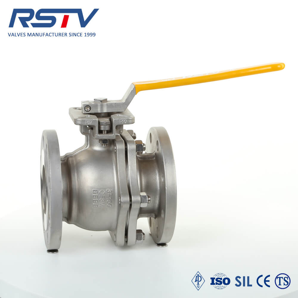
We must compare standard body constructions objectively. The industry utilizes 1PC, 2PC, and 3PC variants. The 2PC floating valve stands out as the ultimate industry standard. It balances structural pipeline integrity perfectly. It also offers excellent ease of factory assembly. We provide a breakdown of common body styles below to assist your selection process.
Body Type | Design Characteristics | Maintenance Accessibility | Leak Paths |
|---|---|---|---|
1PC (One-Piece) | Solid cast body, reduced port flow. | Cannot be repaired inline. Must be discarded. | Fewest external leak paths. |
2PC (Two-Piece) | Two sections bolted or threaded together, full port. | Requires removal from line, easily rebuilt. | One central body joint leak path. |
3PC (Three-Piece) | Center section clamped by end caps. | Center section swings out for inline repair. | Two body joint leak paths. |
Proper material selection prevents catastrophic chemical failures. Let us examine the seats and external body cast.
Soft Seats: Soft seats play a highly critical role. Virgin or filled PTFE remains essential for low-pressure sealing. The material flexibility conforms easily to microscopic scratches on the metal sphere. It seals tightly without requiring massive fluid pressure. It inherently creates the required mechanical pre-load. Virgin PTFE provides maximum softness. Filled PTFE incorporates glass or carbon. This addition increases temperature resistance but reduces slight flexibility.
Body Materials: Metal selection determines physical longevity. Evaluate forged versus cast metal bodies carefully. Forged metal eliminates hidden porosity issues. Cast metal provides a highly economical solution for standard utility lines. Consider the specific gravity of your process media. Corrosiveness dictates the final alloy choice. Stainless steel handles aggressive chemicals beautifully. Carbon steel suits standard industrial water applications perfectly.
Never ignore international testing standards. Verify API 598 compliance before finalizing purchase orders. Standard low-pressure air testing protocols are non-negotiable. Manufacturers test shells pneumatically at roughly 80 PSI. This specific test ensures bubble-tight zero leakage. Industry standards dictate specific hold times based on component size. A small unit might require a fifteen-second hold time. Inspectors watch carefully for zero visible bubbles during this period. Water hydro-testing alone cannot verify low-pressure gas tightness. Always request formal material test reports. Protect your facility from substandard manufacturing practices.
Every mechanical design carries inherent operational limitations. Recognizing these risks prevents unplanned plant shutdowns. You must account for physics when drafting pipeline blueprints.
Constant physical contact carries an unavoidable price. The metal sphere constantly presses into the soft seats. High-frequency automated cycling accelerates this specific seat wear. Trunnion designs suffer slightly less from this issue. Abrasive media particles make this wear even worse. Microscopic grit etches grooves into the PTFE rings. Keep replacement schedules highly proactive. Monitor cycle counts on critical isolation points meticulously.
Avoid specifying floating mechanisms for large-diameter pipelines. Sizes greater than 8 to 10 inches pose physical risks. The sheer physical weight of the sphere causes trouble. Gravity pulls the massive metal ball downward continually. It can permanently deform the bottom soft seat. This cold flow deformation leads to unfixable leaks. Always transition to trunnion designs for massive bore sizes. They support the heavy sphere properly from below.
Low-pressure systems sometimes experience hydraulic spikes. Unexpected high-pressure surges introduce sudden torque locking. The sphere wedges tightly into the downstream polymer ring. Manual actuation becomes physically impossible for operators. Standard lever handles bend under the extreme force. You will need gear operators to force rotation safely. System designers must install pressure relief valves nearby. This protects the isolation hardware from permanent mechanical damage.
Our evaluation highlights crucial engineering principles. Facility managers must apply these insights carefully. Use the following next steps to optimize your pipeline systems today.
Summary of Fit: For low-to-medium pressure applications, the floating design delivers the tightest seal. Its structural reliance on mechanical seat pre-load proves highly effective.
Finalize Bore Sizes: Measure your pipeline dimensions accurately. Restrict floating designs to sizes under 8 inches.
Specify Configurations: Choose the 2PC configuration for standard plant routines. It balances leak prevention and repairability perfectly.
Match Materials: Rigorously match PTFE seat variants to the exact media. Consider temperature limits during this selection.
Call to Action: Consult a sizing specialist today. Review technical data sheets carefully. Match the valve flow coefficient to your specific system drop requirements.
A: Trunnion valves often rely on line pressure pushing spring-loaded seats against a stationary ball. In very low-pressure systems, this pressure may be insufficient to create a tight seal. A floating ball utilizes tight mechanical pre-loading between the seats and the ball. This pre-load guarantees an effective seal regardless of fluid force.
A: It represents a valve body split into two pieces. These pieces are firmly bolted or threaded together. This construction allows for a larger, often full-port ball to be inserted during manufacturing. It offers vastly better fluid flow rates than standard 1PC reduced-port designs.
A: No. Floating ball valves are designed strictly as shutoff components for on/off isolation. Throttling exposes the soft seats directly to high-velocity fluid flows. This exposure causes uneven seat wear rapidly. It completely compromises the low-pressure seal capability.
A: Start by checking for external actuator misalignment. Verify if system pressure is actually too low for the specific seat material's rigidity. Cold flow or debris often causes seat damage. Rebuilding the unit by replacing worn soft seats usually resolves the leak entirely.


