
Views: 0 Author: Site Editor Publish Time: 2026-10-19 Origin: Site


Pressure ratings act as the absolute safety barrier in modern fluid control systems. Engineers must rigorously evaluate these limits. Ignoring them risks catastrophic system failures, hazardous chemical leaks, and severe compliance violations. The wafer type ball valve features a uniquely compact design. Installers secure it by sandwiching the valve body tightly between two pipe flanges. This compression-based installation directly dictates its maximum pressure-handling capabilities. Unlike heavy flanged units, wafer valves rely heavily on surrounding pipe structural integrity. We designed this comprehensive guide for engineers and procurement teams. You will discover a clear framework for evaluating common pressure classes. We will also explore critical material impacts and essential selection criteria for your specific industrial applications. By understanding these parameters, you can safely specify hardware for demanding environments.
Global procurement teams and engineers must standardize pressure terminology. Speaking the same language ensures you specify the correct valves safely. Industry standards dictate exact testing parameters for every valve design. You must align your pipeline specifications to these established global classes.
The North American standard predominantly features Class 150 and Class 300 availability. A Class 150 carbon steel valve handles approximately 285 psi at ambient temperatures. A Class 300 valve steps up to roughly 740 psi under similar conditions. You will rarely find a wafer type ball valve rated Class 600 or higher. The compact body lacks the structural mass necessary to contain extreme internal forces securely.
European fluid control systems rely on PN metrics. PN stands for Nominal Pressure. You will frequently encounter PN16, PN25, and PN40 ratings in metric pipelines. The PN number directly correlates to pipeline design requirements in bar. For example, a PN40 rating signifies a maximum allowable pressure of 40 bar at room temperature.
Manufacturers often cast acronyms directly onto the valve body. WOG stands for Water, Oil, and Gas. CWP translates to Cold Working Pressure. A typical industrial ball valve operates between 800 WOG and 1000 WOG. These thresholds suit most generic utility applications.
Note: Always verify whether your piping system is governed by ASME B16.34 or EN 1092-1 standards before matching a valve’s pressure class, as flange face compatibility directly impacts the valve's pressure-retaining seal.
We must evaluate how different body and seat materials dictate maximum pressure limits. Structural integrity directly relies on these engineering choices. Material science defines the boundaries of your fluid control safety.
A stainless steel wafer ball valve (typically 304 or 316 grade) provides exceptional tensile strength. It also delivers superior corrosion resistance. Engineers choose stainless steel for maintaining pressure integrity in aggressive chemical environments. Carbon steel (WCB) offers high-pressure tolerance primarily for non-corrosive, industrial fluid environments. It remains highly durable but requires protection against rust.
Soft parts almost always fail before the metal body deforms. Polymeric seats represent the true pressure bottleneck in any standard valve design.
Tip: If your application involves both high pressure and abrasive media, specify an industrial ball valve with metal-to-metal seating, as standard PTFE seats will quickly deform or wash out under high-velocity pressure drops.
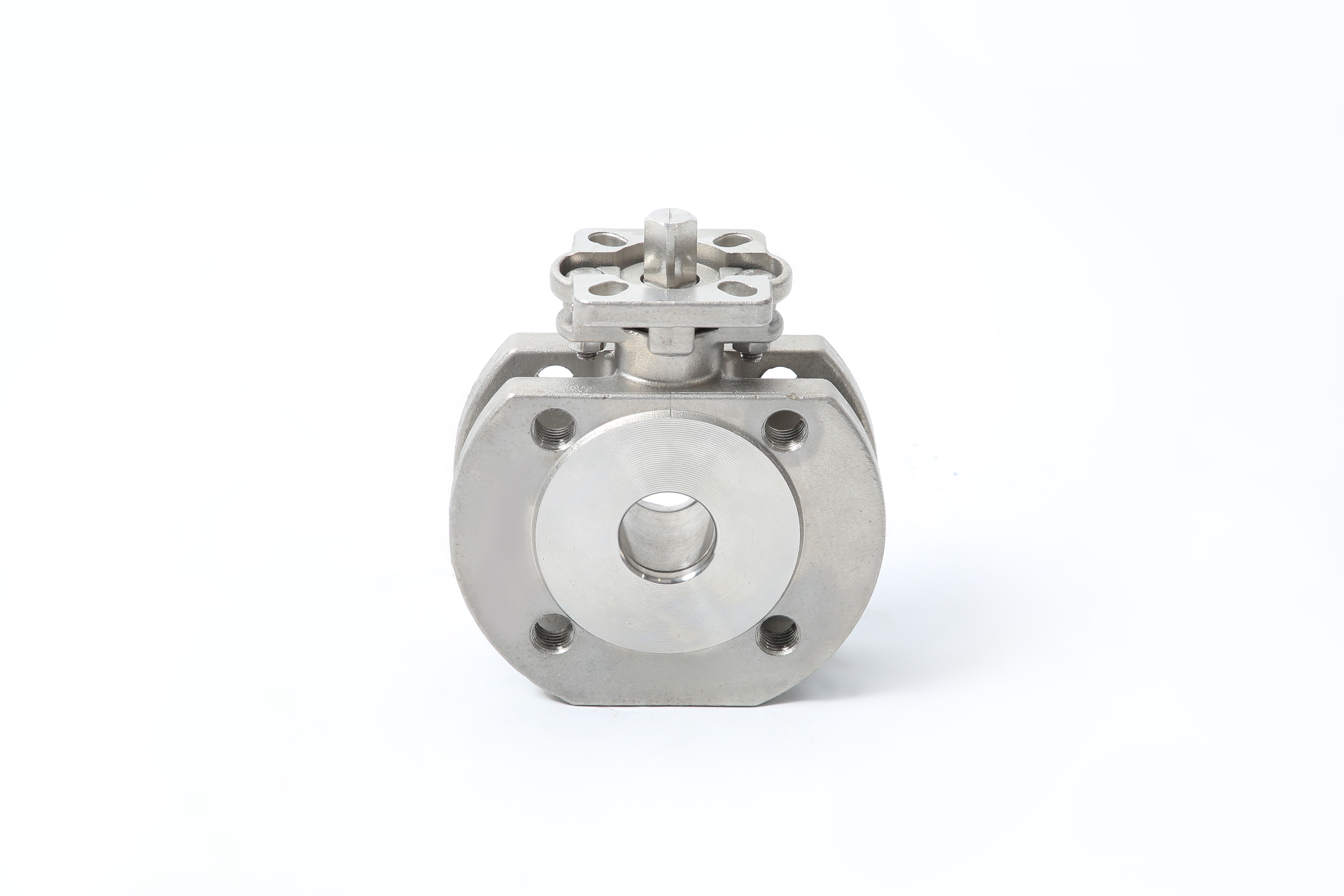
Proper material selection ensures long-term pressure retention in compact wafer valve designs.
Engineers must move beyond static nameplate pressure ratings. You need to understand actual operational capabilities under thermodynamic stress. Real-world applications rarely operate at perfect ambient conditions.
Pressure capacity always inversely correlates with system temperature. As heat rises, polymer and metal yield strengths drop. A valve rated for 1000 psi at 70°F might only safely hold 200 psi at 350°F. Understanding this inverse relationship prevents critical engineering failures.
Fluctuating temperatures cause seat extrusion. Extrusion leads directly to internal bypass leaks. This phenomenon happens even when the static pressure remains well below the valve's maximum rating. The confined polymer expands faster than the surrounding steel, permanently deforming the critical seal geometry.
You must read manufacturer P-T charts to find the true safe operating zone. Steam applications require aggressive derating compared to chilled water systems. We recommend reviewing the exact material test reports for your specific media.
| Temperature (°F) | Virgin PTFE Max Pressure (PSI) | RTFE (Glass-Filled) Max Pressure (PSI) | PEEK Max Pressure (PSI) |
|---|---|---|---|
| 100 | 1000 | 1200 | 2000 |
| 200 | 700 | 900 | 1800 |
| 300 | 300 | 600 | 1500 |
| 400 | Not Recommended | 250 | 1200 |
Maintenance and installation teams must verify specifications directly at the point of installation. Doing so prevents critical system errors. Standardized markings provide immediate verification before technicians pressurize the line.
The valve body contains a wealth of engineering data. You should locate and verify these three specific elements immediately:
Traceability remains crucial for safety-critical industrial ball valve deployments. We rely on heat numbers cast into the body to trace metallurgical origins. Compliance with API 598 testing standards ensures the unit passed rigorous factory pressure tests. You should never install an unmarked valve in a high-pressure system.
Buyers need help deciding if a wafer valve fits their structural needs. Sometimes a standard flanged valve works better. Each design offers specific mechanical advantages and distinct pressure limitations.
Long studs hold wafer valves in compression between two pipe flanges. They save immense space in cramped piping runs. However, this compression load strictly limits extreme pressure handling. Studs can stretch under intense hydraulic shock. Standard flanged valves bolt directly to the pipeline. Their robust two-piece or three-piece bodies handle high-vibration, high-stress, and ultra-high-pressure pipelines much better.
Wafer valves cannot serve as end-of-line valves under pressure. If you remove the downstream pipe, the valve loses its structural compression. Dead-end service requires specifically tapped or lugged designs to maintain seal integrity during maintenance.
Wafer units offer lower initial procurement costs and significantly reduced weight. They require less raw material to manufacture. Buyers must strictly adhere to the pressure envelope. Pushing a wafer valve beyond its intended capability compromises facility safety.
Tip: Do not use a standard wafer type ball valve for dead-end service. If you require end-of-line maintenance capability while the system is under pressure, evaluate a lug-style valve instead.
Here is a practical framework for B2B buyers evaluating their product shortlists. Following these steps ensures mechanical compatibility and system safety.
You must map maximum operating pressure (MOP) and maximum operating temperature (MOT) simultaneously. Never look at pressure limits in isolation. Plot these two variables on a manufacturer-provided curve.
Industrial systems frequently experience dynamic forces. You must factor in water hammer, pressure spikes, and aggressive pump start-up surges. We strongly recommend designing your system using a 1.2x to 1.5x safety factor above standard operating pressure.
Ensure the pipeline flange class matches the valve's structural design. An ANSI 150 flange requires an ANSI 150 compatible valve body. Mismatched classes prevent proper bolt torque and compromise gasket sealing.
Always demand Material Test Reports (MTRs). You should also request certified P-T curves from the manufacturer before finalizing any purchase order. These documents serve as your primary engineering insurance.
Specifying the correct pressure rating for a wafer type ball valve requires looking well beyond the basic CWP or PN number. The true operational limit sits at the complex intersection of system temperature, body metallurgy, and polymer seat composition. A stainless steel wafer ball valve provides excellent baseline integrity, but the internal soft parts ultimately dictate your safety margins. We encourage buyers to consult directly with technical sales engineers. Always reference exact manufacturer P-T charts to ensure safety and long-term system longevity. Proper upfront evaluation prevents hazardous leaks and ensures smooth operational flow.
A: Only if equipped with high-temp seats like PEEK or metal, and strictly within the derated P-T curve limits. Standard PTFE is not recommended for high-pressure steam. Steam temperatures cause standard polymers to extrude quickly.
A: Seat deformation, internal bypass leakage, blown-out stems, or catastrophic structural failure of the valve body. Excessive pressure physically crushes the polymer seals and compromises the metal containment shell.
A: No. 1000 WOG implies 1000 psi at ambient temperatures, whereas ANSI Class 300 has specific pressure/temperature curves dictated by ASME B16.34 and flange face requirements. Class 300 valves undergo different structural testing protocols.


