
Views: 0 Author: Site Editor Publish Time: 2026-10-12 Origin: Site


Pipeline systems face severe catastrophic risks from thermal expansion. Liquid traps easily inside a closed valve cavity during standard operations. Environmental temperatures rise. Adjacent processes radiate heat. This absorbed heat causes the trapped liquid volume to expand rapidly. Massive pressure spikes result immediately. These spikes can deform internal components permanently. Sometimes, the extreme pressure ruptures the entire valve body, releasing hazardous materials.
Unlike floating ball designs, a trunnion mounted ball valve utilizes a fixed ball. It pairs this anchored ball with floating, spring-loaded seats. This unique architecture allows for highly specialized cavity pressure relief mechanisms. Understanding these precise internal mechanics is essential for system safety.
We will explore how self-relieving seats and external relief configurations function. You will learn how to ensure strict API 6D compliance. Selecting the proper relief mechanism prevents catastrophic pipeline downtime. Furthermore, it dictates the correct valve specifications for your specific process media. We will break down the exact engineering principles keeping your pipelines secure.
Fluid physics create significant challenges in pipeline engineering. Operators close a valve fully to halt flow. This action isolates a specific volume of media inside the central body cavity. The fluid sits trapped between the upstream and downstream sealing surfaces.
Trapped liquids are virtually incompressible. They behave much differently than trapped gases. Environmental heat exposes the valve to rising ambient temperatures. Direct sunlight bakes the steel body. Adjacent industrial processes conduct heat through the connecting pipework. The isolated liquid absorbs this thermal energy and expands quickly. Because the liquid cannot compress, the internal cavity pressure skyrockets. This rapid spike often exceeds the structural pressure rating of the valve itself.
Ignoring this thermal expansion brings severe consequences. Operators face several critical failure modes:
Regulatory bodies recognize these severe dangers. API 6D guidelines issue a strict mandate. Pipelines handling liquid mediums subject to thermal expansion must utilize valves equipped with a proven cavity pressure relief mechanism. Engineers cannot bypass this critical safety requirement.
Floating ball valves manage sealing through movement. Pipeline pressure physically pushes the unanchored ball downstream into the seat. Trunnion valves operate on an entirely different mechanical principle. Heavy top and bottom trunnion shafts anchor the ball securely in place. The ball simply rotates on its fixed axis. It cannot shift downstream to relieve built-up pressure. Therefore, the valve relies completely on the dynamic movement of the seats.
Engineers design trunnion seats as independent, floating components. Heavy-duty coil springs sit directly behind the seat rings. These springs push the seats firmly against the fixed ball at all times. This mechanical spring force creates a reliable baseline seal, even at extremely low pipeline pressures.
The system operates on a precise mechanical balance to achieve cavity relief. The internal cavity pressure pushes against the inner diameter of the seat ring. The pipeline pressure and the coil springs push against the outer diameter. A relief threshold triggers when internal cavity conditions change. Cavity pressure exceeds the pipeline pressure plus the mechanical spring force. This overpressure physically pushes the seat ring backward. It compresses the coil springs slightly. The seat pulls away from the ball. Trapped fluid instantly vents back into the pipeline safely.
Temperature variations demand careful engineering calculations. When evaluating a carbon steel trunnion ball valve for an exposed outdoor pipeline, you must analyze ambient temperature swings. Summer heat causes rapid thermal expansion. Calculate the required spring force accurately. The relief threshold must trigger before pressure damages the soft seat inserts.
Valve manufacturers utilize two primary seat designs to manage cavity pressure safely. Engineers categorize these solutions based on how fluid pressure interacts with the seat geometry. Understanding these distinct piston effects guides proper component selection.
The Single Piston Effect (SPE) serves as the standard self-relieving design. Upstream pipeline pressure pushes against the outer face of the seat ring. This force pushes the seat directly into the ball. However, pressure inside the central cavity acts on the inner face of the seat ring. This internal pressure pushes the seat away from the ball. SPE seats provide automatic, built-in cavity relief. They require no external piping or additional safety valves. They offer robust simplicity.
The Double Piston Effect (DPE) focuses entirely on bi-directional sealing. Upstream pipeline pressure pushes the seat against the ball. Unique seat geometry ensures cavity pressure also pushes the seat against the ball. Both pressure sources reinforce the seal. This creates a severe operational risk for liquid applications. The cavity pressure remains permanently trapped. It cannot self-relieve internally through seat movement. Engineers solve this dangerous trap by installing a body-mounted external relief valve.
Engineers evaluate system priorities to choose between SPE and DPE designs. SPE remains the absolute standard for thermal relief in liquid lines. DPE provides superior isolation. You choose DPE when redundant sealing is your highest priority. You sacrifice self-relieving simplicity for absolute isolation security.
| Configuration Metric | Single Piston Effect (SPE) | Double Piston Effect (DPE) |
|---|---|---|
| Cavity Pressure Action | Pushes seat away from the ball. | Pushes seat into the ball. |
| Relief Mechanism | Automatic, internal self-relief. | Requires external relief valve. |
| Primary Advantage | Simplicity and failsafe thermal relief. | Redundant, bi-directional isolation. |
| Ideal Application | Standard liquid pipelines. | Critical gas lines or double isolation needs. |
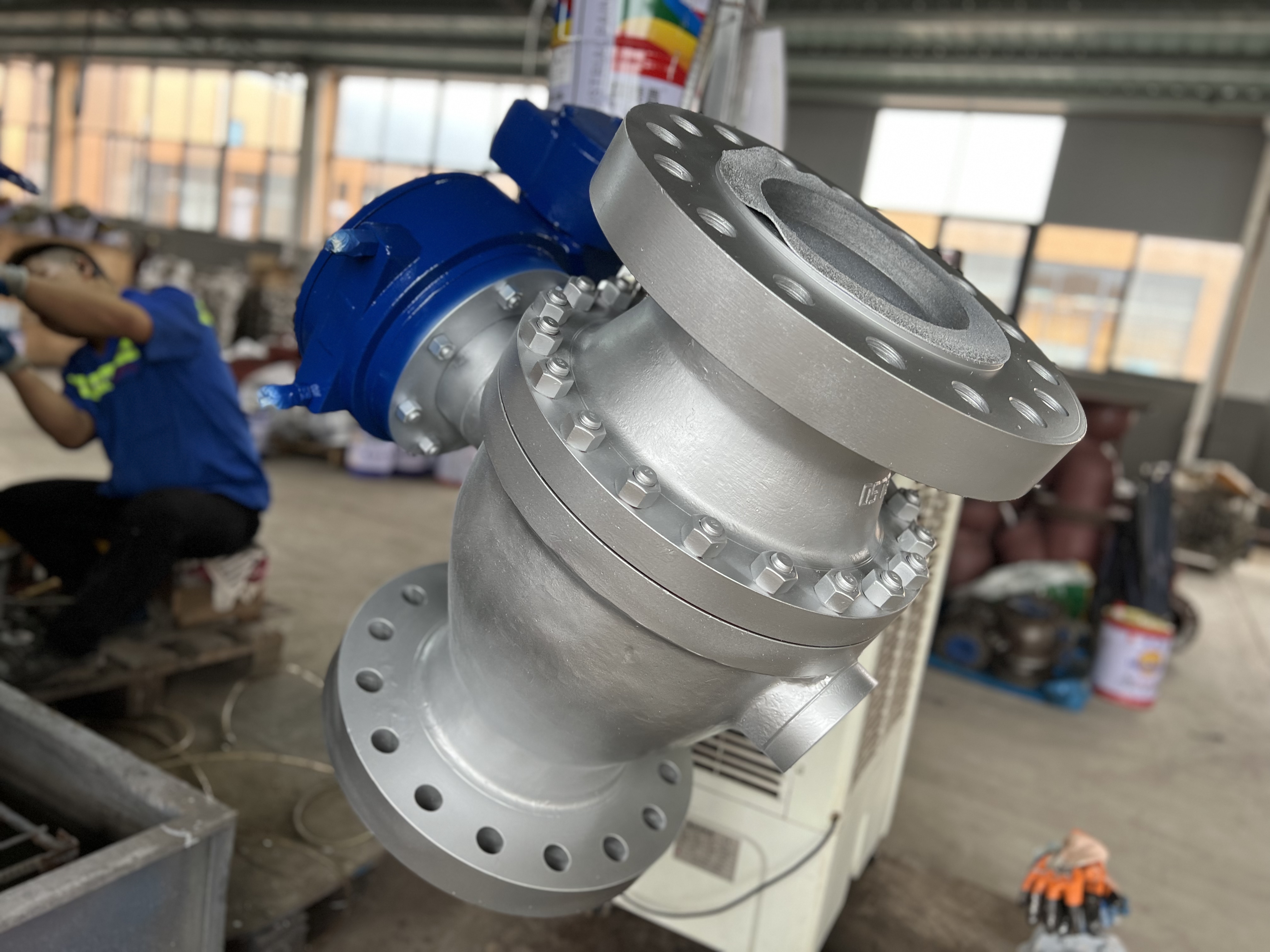
Internal mechanical configuration demonstrating seat movement during cavity overpressure events.
You must connect these physical mechanics to formal procurement standards. The API 6D standard provides the authoritative framework for pipeline valve specifications. Engineers frequently misunderstand critical terminology. This confusion leads to dangerous procurement errors.
Double Block and Bleed (DBB) represents the most common configuration. A standard DBB valve features two SPE seats. It isolates pressure from both the upstream and downstream ends simultaneously. Operators can open a bleed valve to empty the central cavity. If operators leave the valve closed and thermal expansion occurs, the cavity pressure spikes. The SPE seats automatically self-relieve this excess pressure into the pipeline. DBB provides inherent thermal safety for liquid applications.
Double Isolation and Bleed (DIB) offers advanced sealing redundancy. API 6D splits this category into two distinct classifications:
You must exercise extreme caution during procurement. Do not use "DBB" and "DIB" interchangeably in specification documents. Many engineers mistakenly specify a DBB valve when the process actually requires DIB-2 for bidirectional safety. Conversely, specifying a DIB-1 valve for a liquid line without an external relief mechanism invites catastrophic failure. Precise terminology ensures critical compliance during pipeline commissioning.
Theoretical engineering mechanics face harsh realities in the field. Installation environments and process media introduce numerous operational risks. You must evaluate these practical realities before finalizing your specification.
Process media directly impacts seat functionality. Clean liquids flow easily past SPE seats. Particulate-heavy media presents a severe challenge. Crude oil often carries sand, scale, and debris. These solids pack tightly behind the floating seat rings. They foul the internal coil springs. A fouled SPE seat cannot move backward to relieve pressure. The self-relieving mechanism fails silently. In dirty applications, engineers often switch to DPE seats. They utilize an external relief valve instead. Technicians can clean, calibrate, or replace an external relief valve without shutting down the main pipeline.
External relief valves introduce their own unique vulnerabilities. Harsh ambient environments attack external components relentlessly. Small relief valves freeze solid in cold climates. Heavy crude oil clogs their narrow internal passages. Saltwater environments accelerate external corrosion. You must specify heat tracing, heavy insulation, or specialized corrosion-resistant alloys to protect these critical safety components.
Installation constraints also dictate your valve design. Skids and manifolds offer very limited footprint space. A heavy flanged trunnion ball valve requires significant physical clearance. Adding an external relief valve body, isolation tubing, and discharge piping increases the required footprint dramatically. The external assembly might interfere with adjacent piping runs. You must verify horizontal and vertical clearances during the 3D modeling phase.
Always verify the exact set pressure of any external cavity relief valve before installation. Improper calibration destroys the safety margin. Industry standards require precise set points. Set the external relief valve between 1.1 and 1.33 times the valve’s maximum design pressure. This calibration provides a standard safety margin. It prevents premature venting while ensuring absolute protection against thermal body rupture.
Cavity pressure relief remains absolutely non-negotiable for liquid pipeline applications. Ensuring safety depends entirely on the dynamic interaction between the internal springs, floating seats, and the fixed ball. You cannot rely on assumptions when dealing with incompressible fluid thermal expansion. The resulting pressure spikes will rapidly destroy seat integrity or rupture the valve body.
Engineers must audit their specific process data before finalizing procurement. Analyze your process media state. Determine exact ambient temperature variations. Establish your strict isolation redundancy requirements. Use this empirical data to select between SPE, DPE, or hybrid DIB-2 seat arrangements confidently.
We encourage you to consult with technical valve specialists early in the design phase. Specialists help calculate precise relief set-pressures accurately. Always demand and review formal API 6D Factory Acceptance Testing certificates. Rigorous verification before final procurement guarantees your pipeline remains safe, compliant, and continuously operational.
A: Unrelieved thermal expansion creates immense internal pressure. This extreme force crushes the soft thermoplastic seat inserts. It can lock the ball in place, preventing the actuator from turning the stem. Under extreme conditions, the pressure ruptures the valve body or shears the bolting, causing hazardous environmental leaks.
A: Generally, no. Floating valves rely on pipeline pressure moving the entire ball downstream into the seat to create a seal. They naturally trap pressure inside the upstream cavity. They require special internal modifications, like a pressure equalization hole drilled directly through the upstream side of the ball, to prevent overpressure.
A: Manufacturers verify this during Factory Acceptance Testing (FAT). They perform a rigorous hydrostatic test. Technicians close the valve and pressurize the internal cavity independently of the main line. They measure the exact pressure at which the SPE seat vents or the external DPE valve pops, recording it against API 6D standards.


