Views: 0 Author: Site Editor Publish Time: 2026-06-15 Origin: Site


Implementing reliable flow control in heavily congested piping systems, skids, or compact machinery represents a core engineering challenge. Planners constantly fight for every millimeter of clearance when designing modern industrial modules. Standard flanged valves demand extensive face-to-face dimensions. They simply do not fit into tight-space installations easily. Forcing oversized components into confined layouts complicates future maintenance routines. Oversized units also drastically increase overall system weight. You need a more mathematically sound approach. A wafer type ball valve offers a specific, proven solution. It reduces spatial footprint and pipeline weight without sacrificing full-port flow capabilities. This comprehensive guide covers the critical technical evaluation steps required. We will explore installation realities and specific evaluation criteria needed to deploy these valves successfully. You will learn proven alignment protocols to optimize your next compact piping project effectively.
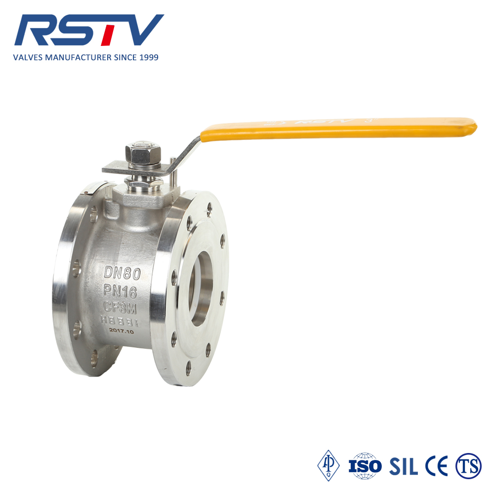
Spatial Efficiency: Wafer type ball valves significantly reduce face-to-face installation dimensions and overall pipeline weight compared to traditional flanged equivalents.
Actuation Readiness: Specifying an ISO5211 wafer ball valve ensures standardized, direct-mount automation without the need for custom bracket fabrication.
Material Selection: An SS wafer valve (316 stainless steel) offers the most versatile baseline for corrosion resistance and structural integrity across Class 150/300 applications.
Installation Precision: Successful deployment requires strict adherence to flange alignment and bolt-torquing sequences to prevent valve body binding or seat deformation.
Engineers face severe dimensional problems daily. Traditional two-piece or three-piece flanged valves fail repeatedly in skid manufacturing. They also fail in compact OEM equipment layouts. These traditional valves carry excessive face-to-face lengths. They present bulkier weight profiles. You simply cannot wedge them into dense piping manifolds.
Enter the compact ball valve. This ingenious wafer design removes bulky end flanges entirely. The flangeless body clamps tightly between two adjacent pipe flanges. This configuration reduces valve length by up to 30% to 50%. You immediately gain crucial layout flexibility. Designers can pack more functionality into smaller modular skids.
Weight reduction matters significantly in structural engineering. Less component weight minimizes stress on pipeline supports. It eases the heavy burden on pipe hangers. You will notice this benefit particularly in vertical pipe runs. Thin-wall piping systems also benefit greatly from reduced mechanical load. Lighter valves prevent sagging and reduce long-term pipe fatigue.
You must consider the trade-offs transparently before specification. A wafer ball valve lacks the inline maintenance ease of a true three-piece valve. You cannot easily drop the center section out for quick repairs. Furthermore, we do not recommend them for dead-end service. You must install a downstream blind flange. This secures the valve safely under pressure if you remove the downstream piping.
Valve Type | Space Requirement | Weight Profile | Inline Maintenance |
|---|---|---|---|
Standard Flanged (2-piece) | High (Long face-to-face) | Heavy | Difficult (Requires pipe removal) |
Standard 3-piece | Moderate | Moderate to Heavy | Easy (Swing-out center body) |
Wafer Type | Very Low (Ultra-compact) | Lightweight | Difficult (Requires pipe spreading) |
You must evaluate pressure and temperature limits strictly during the planning phase. Align the valve body design properly. Match internal seat materials to your system requirements. Standard operations typically use PTFE (Polytetrafluoroethylene) or RTFE (Reinforced PTFE). These materials perform excellently for Class 150 to Class 300 equivalent ratings. Exceeding temperature limits causes immediate internal seat failure.
Material selection dictates operational longevity. An SS wafer valve typically utilizes CF8M or 316SS alloys. This serves as the default standard globally. We use it extensively across chemical processing, food production, and general industrial applications. Stainless steel resists corrosion far better than standard carbon steel variants. It ensures superior structural integrity over thousands of open-close cycles.
Port size heavily impacts overall system performance. You must differentiate between standard bore and full port designs carefully. Wafer configurations can easily offer full port flow. This ensures you meet required Cv (flow coefficient) values consistently. You avoid unwanted pressure drops across the valve body. Full port designs allow unobstructed media flow.
Automation demands scalability in modern plants. Specifying an ISO5211 wafer ball valve creates a strong engineering case. A standardized direct-mount pad eliminates tedious alignment issues. It significantly reduces the overall height profile above the pipe. You can easily add pneumatic or electric actuators later. You never need custom fabricated mounting brackets.
PTFE Seats: Excellent chemical resistance, suitable for temperatures up to 400°F (204°C).
RTFE Seats: Fiberglass reinforced, provides better wear resistance and handles slightly higher pressures.
Metal Seats: Required for abrasive media or extreme temperatures exceeding 500°F (260°C).
Proper piping preparation prevents disaster during installation. Ensure adjacent pipe flanges remain perfectly parallel. Space them correctly prior to valve insertion. Misalignment ruins internal valve seats instantly. Installers often overlook this critical step. You must verify flange parallelity using precision tools.
Gasket selection requires strict adherence to rules. Select high-quality ring gaskets carefully. They must match both the valve face texture and the pipeline media chemistry. Ensure they do not protrude into the flow path during compression. Protruding gaskets cause severe turbulence. They also trap dangerous debris inside the pipeline.
Handling and positioning demand specific best practices. Center the wafer body perfectly between the two pipe flanges. Use designated centering alignment holes if the manufacturer provides them. Alternatively, use standard structural bolts to guide the heavy body into place. Never let the valve rest entirely on the lower bolts during positioning.
Risk mitigation requires constant vigilance. Never use the valve to "pull" misaligned piping together. This induces severe mechanical stress directly on the valve body. It distorts the internal ball. It eventually ruins the primary fluid seal. You must correct pipe alignment before tightening any bolts.
Clean all pipe flange faces thoroughly using a wire brush and appropriate solvent.
Inspect the wafer valve faces for any shipping damage, scratches, or protective covers.
Verify the gap between pipe flanges provides enough clearance for the valve body plus two gaskets.
Insert the bottom flange bolts first to create a secure resting cradle for the valve body.
The "criss-cross" torquing pattern remains absolutely mandatory. Execute a strict star-pattern bolt tightening sequence always. This technique ensures uniform compression across the delicate valve faces. Uneven compression guarantees future media leaks. It also damages the internal sealing geometry permanently.
Highlight torque specifications clearly for your field technicians. Adhere strictly to the specific manufacturer torque values. Do not rely on generic standard pipeline bolt torques. Wafer valves require delicate balance. Over-tightening crushes the internal PTFE components irreparably. Under-tightening fails to secure the necessary pressure boundary.
Troubleshooting a "valve not closing" scenario happens frequently. This common adoption risk stems directly from uneven flange torquing. Poor tightening sequence compresses the internal seats asymmetrically. The stainless steel ball binds tightly against the deformed PTFE. The valve completely fails to close or open smoothly.
Post-installation testing prevents major system failures. Always dry-cycle the newly installed valve prior to system pressurization. Turn the actuation handle fully open and fully closed several times. Confirm unimpeded operational torque manually. You must verify smooth movement before introducing dangerous or highly pressurized fluid into the system.
Step 1: Hand-tighten all flange nuts to lightly compress the gaskets and center the valve.
Step 2: Tighten bolt 1 to 30% of final torque, then move to the bolt diagonally opposite.
Step 3: Tighten the opposite bolt to 30%, then move to the next adjacent bolt.
Step 4: Repeat the star pattern at 60% torque, and finally at 100% torque.
Procurement teams must focus heavily on compliance and certification. Verify necessary industry standards based on your specific application requirements. Look for API 608 compliance for reliable ball valve design parameters. Confirm fire-safe API 607 ratings if you handle flammable or combustible media. Ensure CE/PED requirements meet strict regional safety codes.
Assess vendor technical support deeply during the selection phase. Supplier reliability matters enormously during complex modular installations. Check their availability of accurate 3D CAD models. Design planners find these models absolutely crucial for spatial planning in tight skids. Reliable CAD files prevent costly interference issues down the line.
Demand comprehensive documentation from your supplier. Request detailed material test reports (MTRs) for every unit. MTRs verify the exact metallurgical quality of the stainless steel components. Look for clear, comprehensive installation manuals. Good manuals guide field teams away from common torquing and alignment errors. Strong vendor support saves countless hours of frustration during the commissioning phase.
The wafer style configuration delivers immense strategic value. Engineering teams facing rigid spatial constraints desperately need this compact solution. It shrinks physical installation footprints drastically while maintaining optimal full-port flow rates. You gain significant weight reductions across your entire piping network.
Long-term success depends equally on precise engineering specification and strict field execution. You must select correct internal materials and specify standardized direct-mount pads. You must enforce highly disciplined installation practices. Field teams must respect alignment rules and strict torquing patterns.
Consult an experienced valve application engineer early in your layout design phase.
Review all piping schematics thoroughly to identify potential dead-end service risks.
Request exact dimensional data sheets and integrate them into your skid CAD models immediately.
Establish a clear, documented bolt torquing procedure for your installation crews.
A: Standard ratings typically match ASME Class 150 or Class 300, equivalent to PN16 or PN40. The absolute maximum pressure limits depend heavily on the specific body design and the chosen internal seat materials. PTFE seats usually limit high-temperature pressure capabilities compared to reinforced RTFE options.
A: We strongly advise against using them for true dead-end service. Because they lack standard flanged ends, they rely on two pipe flanges for structural integrity. You must install a solid downstream blind flange to safely secure the valve and contain system pressure.
A: Difficult operation almost always results from uneven flange bolt tightening or severe pipe misalignment. When you over-torque or unevenly tighten the structural bolts, you compress the internal PTFE seats asymmetrically. This causes the metal ball to bind tightly against the deformed seat.
A: No. The integrated direct-mount pad eliminates the need for separate brackets. You mount the pneumatic or electric actuator directly onto the valve body. This standard configuration saves valuable vertical space and prevents stem alignment issues over time.
A: The valve seals using standard pipeline ring gaskets. You place these gaskets between the pipe flanges and the valve body faces. As you tighten the flange bolts, the compression clamps the gaskets against the serrated or smooth faces of the valve, creating a fluid-tight boundary.


