
Views: 0 Author: Site Editor Publish Time: 2026-11-09 Origin: Site


Threaded ball valves act as critical control points in both industrial pipelines and residential plumbing. You rely on them daily to manage fluid flow safely and effectively. While the installation process might seem straightforward at first glance, improper techniques often cause hidden leaks and structural damage. The long-term integrity of your piping system heavily depends on precise thread sealing. It also requires strict torque management during assembly.
This guide walks you through a professional-grade workflow for securing NPT and BSPT connections. You will learn how to verify material specifications before picking up a wrench. We cover practical methods to avoid mechanical stress and eliminate contamination risks. Mastering a proper threaded ball valve installation ensures optimal performance and prevents dangerous system failures down the line.
Before you begin any mechanical work, you must verify all component specifications. A successful installation starts with ensuring your valve matches the piping system perfectly.
Pipe threads are not universally interchangeable. You must differentiate between NPT (National Pipe Taper) and BSPT (British Standard Pipe Taper). NPT threads feature a 60-degree flank angle. BSPT threads use a 55-degree flank angle. Forcing an NPT valve onto a BSPT pipe causes immediate mechanical incompatibility. This mismatch strips the threads and guarantees a high-pressure leak. Always check the valve body stamp to confirm the standard matches your pipe.
You must assess material suitability based on fluid chemistry and environmental conditions. Stainless steel offers excellent corrosion resistance for aggressive chemicals and high-moisture environments. Alternatively, a Carbon Steel Threaded Ball Valve provides a rugged, highly durable option for non-corrosive oil, gas, and high-pressure steam applications. Selecting the wrong material leads to rapid degradation and premature failure.
Every valve carries specific pressure and temperature ratings, often denoted as WOG (Water, Oil, Gas) or CWP (Cold Working Pressure). You must validate these plate ratings against the actual operating parameters of your system. Installing a valve rated for 1000 PSI in a system experiencing 1500 PSI pressure spikes creates a severe safety hazard. Verify thermal limits as well, since extreme heat can melt internal PTFE seats.
Inspect the valve body for a flow direction indicator. Most ball valves operate bi-directionally. However, best practice dictates standardizing the orientation across your facility. Installing the valve so the handle faces a specific direction when closed improves maintenance clarity. If the valve features a directional arrow, you must align it with the media flow path.
Professional results require the right tools and rigorous system preparation. Rushing this phase often introduces debris into the sealing surfaces.
Gather all necessary equipment before shutting down your system. You will need two pipe wrenches to execute the mandatory two-wrench method. Keep wire brushes handy for cleaning pipe ends. Select a high-quality pipe sealant appropriate for your specific media and temperature range.
| Tool / Material | Primary Purpose | Professional Tip |
|---|---|---|
| Two Pipe Wrenches | Counter-holding and tightening | Use smooth-jaw wrenches on brass to avoid gouging. |
| Wire Brush | Thread cleaning | Use a stainless steel brush to prevent rust transfer. |
| PTFE Tape (Teflon) | Thread lubrication and sealing | Use high-density tape (yellow for gas, pink for water). |
| Liquid Pipe Dope | Vibration resistance | Ensure compatibility with your pipe material. |
Never break into a live piping system. Follow strict safe shutdown procedures. Isolate the section by closing upstream and downstream valves. Depressurize the line completely. Drain all residual fluid from the piping section into appropriate containers. Implement Lockout/Tagout (LOTO) protocols to ensure nobody accidentally restores pressure while you work.
Clean all pipe ends thoroughly. Use your wire brush to remove burrs, old tape, or hardened pipe dope from the male threads. Inspect the threads for flat spots or cross-threading damage. Any remaining debris can easily travel into the valve body. Debris compromises the soft PTFE seats and prevents the ball from sealing tightly.
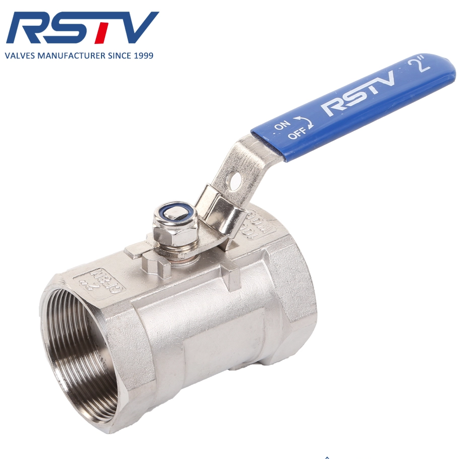
The actual assembly requires patience and strict mechanical discipline. We will focus on sealing techniques and torque application to ensure a permanent, leak-free joint.
Proper sealant technique determines the success of your connection. PTFE tape acts primarily as a thread lubricant, preventing galling. Apply the tape in a clockwise direction—the same direction you will turn the valve. Wrap it tightly three to four times. You must leave the first thread completely free of tape. If tape overlaps the pipe edge, fluid flow will shear it off. These tape shreds will enter the chamber and damage the soft seats.
For high-vibration systems, you can apply a thin layer of liquid sealant over the PTFE tape. Brush it lightly onto the male threads only. Avoid pushing excess dope into the piping.
You must protect the valve body from rotational stress. Always use the two-wrench method. Place one wrench on the pipe directly adjacent to the fitting. Place the second wrench on the hex end of the valve you are attaching. Never span the valve body with your wrench. Turning the valve body directly against a fixed pipe creates dangerous stress concentrations. This error easily twists and ruins a 2PC Threaded Ball Valve by breaking the factory seal between its two halves.
Follow the "hand-tight plus" rule for proper thread engagement. First, thread the valve onto the pipe by hand until it stops smoothly. Once hand-tight, use your wrenches to turn the fitting an additional one to two full turns. Tapered threads wedge together tightly to create the seal. You do not need to bottom out the threads. Applying measured torque increments achieves a leak-proof seal without straining the structure.
Stop tightening when the handle reaches an optimal position. You must ensure the handle remains accessible and unobstructed. It needs enough clearance to swing through its full 90-degree arc. Emergency shut-off access is critical. If the handle hits a wall or another pipe, you cannot close the valve quickly during an emergency.
Installation does not end when you tighten the last thread. Rigorous testing and preventative maintenance guarantee the system will operate reliably over its intended lifespan.
Restore system pressure slowly. Begin with a low-pressure visual inspection. Look closely at the thread joints and the valve stem for any moisture or weeping. Gradually ramp up to full operating pressure. Sudden pressure spikes can hammer the piping and dislodge newly seated thread sealants.
Once pressurized, exercise the valve through its full range of motion. Open and close it several times. The handle should turn smoothly. If you feel excessive resistance or internal binding, you likely overtightened the connection. Overtightening compresses the internal seats against the ball.
Implement a preventative maintenance schedule to protect your investment. A high-quality Stainless Steel NPT BSPT BSP Ball Valve demands very little upkeep, but you should still perform quarterly visual inspections. Check the stem packing nut. If you spot a minor drip near the handle, you can often stop it simply by tightening the packing nut a quarter-turn.
Recognize the common failure indicators to avoid unexpected blowouts. You must replace the component if you observe:
Experience teaches us what to watch out for. Most valve failures trace back to human error during the initial assembly. By anticipating these pitfalls, you can design a more resilient system.
More torque does not equal a better seal. Excessive force leads to cracked valve bodies or permanently deformed pipe threads. Tapered threads generate immense outward radial force as you tighten them. If you overtighten a cast body valve, it will split down the side. Stick strictly to the hand-tight plus one-to-two turns rule.
Keeping the internals clean is paramount. Pipe cuttings, rust flakes, or tape shreds entering the ball chamber act like sandpaper. They score the polished steel ball and shred the soft Teflon seats. Once the seat scratches, the valve will never hold pressure completely. Thoroughly flush pipes if you performed cutting or threading operations upstream.
Plan for the future when assembling your system. Incorporate union fittings or flanges near the valve. This strategy allows for easy replacement without requiring major pipe rework. If you hard-pipe a valve directly into a fixed run on both sides, you will have to cut the pipe to remove it later. A thoughtful Thread End Ball Valve installation includes unions on at least one side to facilitate rapid, painless maintenance.
| Failure Mode | Root Cause | Prevention Strategy |
|---|---|---|
| Body Cracking | Excessive wrench torque | Limit wrench turns past hand-tight; avoid cheater bars. |
| Internal Leakage | Debris scratching the seat | Leave first thread bare of tape; deburr pipes thoroughly. |
| Center Joint Leak | Twisting across the valve body | Strictly apply the two-wrench technique on the valve end. |
| Galling | Dry stainless threads | Use high-density PTFE tape or specialized anti-seize paste. |
Professional installation stands as your best investment in long-term system reliability. By adhering to standardized thread procedures and employing the two-wrench methodology, you significantly reduce the risk of downtime and costly leaks. Always prioritize safety by depressurizing lines fully before starting. Verify your material ratings against operating pressures. Finally, design your pipe runs with unions so the valve remains accessible for its entire lifecycle. Following these proven techniques ensures a secure, high-performing fluid control system.
A: Both serve excellent purposes. PTFE tape provides great lubrication and ease of use for general plumbing. We recommend using liquid thread sealants (pipe dope) in high-vibration environments, as they cure and resist shaking better. Many professionals combine both: applying tape first, then adding a thin layer of dope on top.
A: Most ball valves feature a bi-directional design, meaning they handle flow from either side equally well. However, standard practice recommends installing them with a consistent handle orientation across your facility. If the manufacturer casts a directional arrow on the body, you must follow it.
A: The two-wrench method involves using one wrench to hold the pipe stationary and a second wrench to turn the valve end fitting. It prevents you from transferring rotational stress through the valve body. Twisting the body directly often breaks the factory seal between the valve pieces.
A: We utilize the "hand-tight plus 1-2 turns" standard. First, thread the valve by hand until it stops. Then, use your wrenches to tighten it an additional one to two full rotations. Mechanical over-stressing will crack the valve body or distort the internal ball seats.
A: Yes. We strongly suggest installing a union fitting on at least one side of the valve. A union allows you to break the piping connection quickly. This eliminates the need to cut the pipe or disassemble large sections of the system during future maintenance.


