
Views: 0 Author: Site Editor Publish Time: 2026-11-14 Origin: Site


The reliability of a flow control system depends heavily on the precision of its installation. For gate valves, improper seating or alignment is a leading cause of premature failure, seat leakage, and costly unplanned downtime. This guide provides a technical framework for the installation and commissioning of gate valves, covering standard industrial protocols, material-specific considerations, and the validation steps necessary to ensure long-term operational success. Whether working with Cast Steel gate valves for high-pressure applications or Stainless Steel units for corrosive environments, adhering to these structured procedures is essential for compliance and performance. You will learn how to handle, mount, and verify your equipment to maximize service life and maintain system integrity.
Verification is Primary: Always verify that the valve pressure rating (e.g., 150LB or 300LB flange classes) aligns with the piping system's design limits before installation begins.
Alignment Over Force: Never use the valve to compensate for misaligned piping; proper spool alignment is the only way to prevent mechanical stress on the valve body.
Strategic Tightening: Follow a cross-pattern (star) bolting sequence to ensure uniform gasket compression and prevent flange leakage.
Commissioning is Essential: Do not skip hydrostatic testing or actuator stroke verification; these are the final checks for sealing integrity and operational responsiveness.
Material Awareness: Installation torque and handling requirements differ between Cast Steel (carbon steel) and Stainless Steel; treat each according to its specific metallurgy and susceptibility to surface damage.
Before the valve reaches the piping system, verification of technical specifications is a critical risk-mitigation step. Skipping this phase is the most common cause of "failure-on-startup."
Conformance Check: Cross-reference the valve tag with the P&ID. Confirm that the pressure class—such as a 150LB Flanged Gate Valve or a 300LB Flanged Gate Valve—matches the system design pressure.
Damage Assessment: Inspect internal components for debris. Check the packing gland tightness and the condition of flange faces. You must address any nicks on raised face flanges before mating.
Port Cleanliness: Remove protective end caps only immediately before installation. This prevents environmental debris like grit or welding slag from entering the seat area.
Environmental Considerations: For a Stainless Steel Gate Valve, ensure the storage area remains free of carbon steel contamination. This simple step prevents galvanic corrosion and pitting.
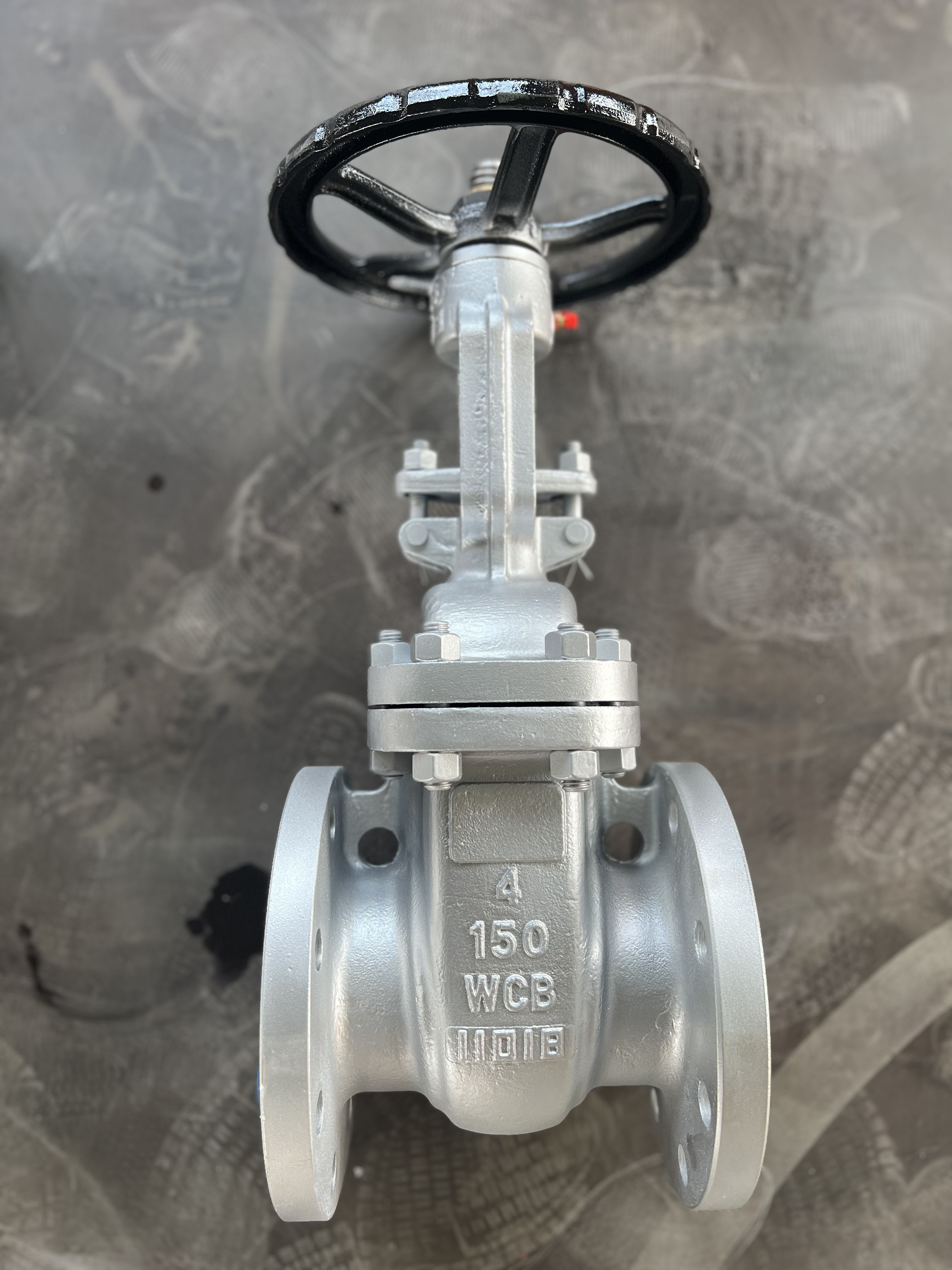
The goal of mechanical installation is to place the unit in the system without inducing stress on the body. Improper handling often leads to premature bonnet deformation or stem misalignment.
Piping must be properly supported and aligned. If flange faces are not parallel, do not use bolts to pull the pipe into position. This creates significant bending moments that deform the body and cause seat leakage. You must match the gasket material to the fluid service and temperature. A misaligned gasket creates a localized pressure point that compromises the seal.
Follow these steps for optimal bolting:
Lubricate bolt threads to ensure accurate torque readings during assembly.
Tighten bolts using a star pattern to ensure even pressure distribution.
Perform tightening in at least three stages. Use 30%, 60%, and 100% of final torque values.
Always confirm if the application requires a specific flow direction. If the Gate Valve is unidirectional, ensure the arrow on the body matches the flow direction. Consult the manufacturer’s documentation for specific stem orientation requirements.
Installation is complete only after the system has been tested under dynamic conditions. You must prove the valve operates correctly before declaring the line operational.
Once installed, perform a system-wide hydro-test to check for leaks. Inspect the body-to-bonnet seal and all flange connections for signs of weeping. If you detect a leak, never tighten bolts under pressure. You must depressurize the system entirely before attempting any adjustments.
Next, perform stroke verification. Manually operate the valve or cycle the actuator through its full range. Ensure the gate travels freely and seats firmly without binding. For wedge-gate designs, verify that the valve achieves "bubble-tight" shutoff as specified by industry standards like API 598. Finally, perform a minor "snug" adjustment on the gland packing to accommodate initial seating. Do not overtighten, as this increases stem friction and causes unnecessary wear.
Different valve types require subtle adjustments in handling, particularly when comparing heavy-duty Cast Steel Gate Valve models to corrosion-resistant alternatives.
Cast steel units frequently handle high-temperature steam or hydrocarbon services. Thermal expansion is a critical factor in these applications. You must ensure that pipe supports allow for movement so the valve does not become the anchor point. Conversely, stainless steel is often softer than carbon steel. Overtightening flange bolts on stainless steel can lead to galling of the threads. Use approved anti-seize compounds to protect the threads at operating temperatures.
Table 1 provides a summary of handling considerations for various material classes.
Valve Material and Handling Summary
Valve Material | Primary Handling Concern | Recommended Best Practice |
|---|---|---|
Cast Steel | Thermal expansion stress | Ensure proper piping support and thermal relief |
Stainless Steel | Thread galling and pitting | Apply anti-seize and avoid carbon contamination |
Pressure Class | Incorrect hardware sizing | Use calibrated torque wrenches per IOM specs |
Reviewing common pitfalls helps your team establish a robust quality assurance process. Mistakes during gate valve installation often stem from oversight rather than equipment failure.
The "Debris Trap" Error: Never install a valve in a line that has not been flushed. Construction debris like welding rods or sand trapped in the seat will damage the sealing surfaces during the first closure.
Overtightening the Stem: Many users mistake "closing hard" for "closing tight." Once the gate is seated, further force only puts stress on the stem threads and bonnet assembly.
Ignoring Thermal Expansion: In hot oil systems, the valve body and piping will expand. Failing to account for this can lead to loose bolts or overstressed fasteners, resulting in eventual fatigue failure.
Successful gate valve installation is a combination of rigorous preparation, disciplined execution, and thorough commissioning. By prioritizing alignment, following standardized torque patterns, and respecting specific material properties, your maintenance teams can significantly extend the life of their flow control assets. Always consult the specific manufacturer documentation, as individual designs may require unique procedural adjustments. To improve your facility's reliability, consider these next steps:
Standardize your pre-installation inspection checklists.
Train maintenance staff on correct cross-pattern torque procedures.
Maintain accurate records of hydrostatic test results for each valve.
Use the correct valve class, whether it is a standard cast steel unit or a specialized alloy, to meet system requirements.
A: While most gate valves can be installed in a horizontal or vertical line, the preferred orientation is with the stem pointing straight up. Installing with the stem facing downwards can cause the bonnet cavity to act as a trap for debris, which can eventually prevent the valve from closing fully.
A: Yes. In high-temperature applications, it is standard practice to re-check bolt torque after the system has reached operating temperature and stabilized. Thermal expansion can alter the stress on the fasteners, requiring a final verification.
A: The primary difference is the flange thickness, bolt hole diameter, and bolt quantity. 300LB valves are designed for higher pressures and typically require a higher torque value for the fasteners. Always follow the manufacturer’s torque chart for the specific valve class.
A: If the valve becomes difficult to open or close—requiring significantly more torque on the handwheel than usual—the packing gland is likely overtightened. The packing should be tight enough to prevent leakage but loose enough to allow the stem to operate smoothly.


