
Views: 0 Author: Site Editor Publish Time: 2024-12-26 Origin: Site


Did you know valves are the silent rulers of nearly all the industries? Be it oil, or gas, or food processing industry, valves are crucial in terms of flow control for liquids and gases.
But how an engineer can communicate the operation or layout of valves within complex piping systems? The answer is valve symbols and P&ID (Piping and Instrumentation Diagram).
Within this article, we would like to take you further into the world of valve symbols and P&ID diagrams. You are going to learn how to read and interpret these important resources and discover their significance in designing operating and maintaining industrial processes.
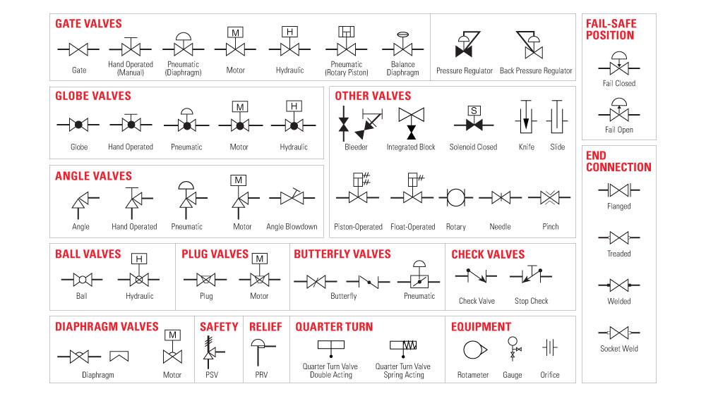
A Piping and Instrumentation Diagram (P&ID) is a detailed schematic that represents the layout and function of piping, equipment, instrumentation, and control systems in an industrial process. It provides a comprehensive overview of the system, showing the interconnections between components and the flow of materials and signals.
The primary purpose of a P&ID is to communicate the design intent and operational logic of a process system. It serves as a blueprint for engineers, operators, and maintenance personnel to understand how the system works and how to troubleshoot issues.
Key purposes of P&IDs include:
Documenting the process design
Facilitating communication between disciplines
Serving as a basis for system control and automation
Providing information for safety and risk analysis
Assisting in maintenance and troubleshooting
P&IDs use a standardized set of symbols to represent various components in the system. These symbols are generally consistent across industries, allowing for clear communication and understanding.
Common components and symbols found in P&IDs include:
Piping and fittings
Valves (e.g., gate, globe, ball, check valves)
Equipment (e.g., pumps, tanks, heat exchangers)
Instrumentation (e.g., sensors, transmitters, gauges)
Control devices (e.g., controllers, actuators)
Signal lines (e.g., electrical, pneumatic, hydraulic)
Understanding P&IDs is crucial for effective design, operation, and maintenance of industrial processes. They provide a common language for communication between various stakeholders involved in the project.
During the design phase, P&IDs help engineers to:
Develop and refine the process design
Identify potential issues and optimize the system
Ensure proper sizing and selection of equipment
In the operation and maintenance phases, P&IDs are used to:
Train operators on the system's functionality
Develop operating procedures and control strategies
Troubleshoot and diagnose issues
Plan and execute maintenance activities
While both P&IDs (Piping and Instrumentation Diagrams) and PFDs (Process Flow Diagrams) are essential tools for representing industrial processes, they serve different purposes and contain varying levels of detail.
The main differences between P&IDs and PFDs lie in their level of detail, scope of application, and complexity.
| Aspect | P&ID | PFD |
|---|---|---|
| Level of Detail | High | Low |
| Scope of Application | Detailed Engineering | Conceptual Design |
| Complexity | High | Low |
PFDs provide a simplified, high-level overview of the process, focusing on major equipment and material flow paths. They do not include details such as piping sizes, instrumentation, or control loops.
In contrast, P&IDs are much more detailed, showing all relevant information needed for the design, construction, and operation of the system. They include:
Piping sizes and materials
Valve types and specifications
Instrumentation and control devices
Equipment details and identification numbers
PFDs are primarily used in the early stages of a project, during the conceptual design phase. They help engineers understand the overall process flow and identify the main equipment required. PFDs are also useful for communicating the process concept to non-technical stakeholders.
P&IDs, on the other hand, are used in the detailed engineering phase. They provide the necessary information for the actual design, procurement, construction, and operation of the system. P&IDs are essential for:
Detailed system design
Equipment and instrument specification
Control system programming
Operational procedures and training
Due to their high level of detail, P&IDs are more complex than PFDs. They require a thorough understanding of the process, equipment, and control philosophy. P&IDs use a comprehensive set of symbols and notations, which can be challenging for those not familiar with the standard.
PFDs, being more simplistic, are easier to read and understand, even for people with limited technical knowledge. They use fewer symbols and focus on the overall process flow, making them more accessible to a broader audience.
Valves are essential components in any piping and instrumentation system. They control the flow of fluids, regulate pressure, and ensure safety. Understanding their symbols in P&ID diagrams is essential for design, operation, and maintenance.

Symbol Representation: A rectangular box with a horizontal line.
Function and Usage: Stops or allows fluid flow. Ideal for on/off control, offering minimal resistance when fully open.

Symbol Representation: A rectangular box with a smaller solid circle inside.
Function and Usage: Regulates fluid flow. Suitable for precise flow control in pipelines.

Symbol Representation: A circle with a smaller circle or horizontal line inside.
Function and Usage: Provides on/off control with minimal pressure loss. Common in systems needing quick shutoff.

Symbol Representation: A circle bisected by a diagonal line.
Function and Usage: Controls flow using a rotating disc. Lightweight and compact, ideal for tight spaces.

Symbol Representation: A circle with an arrow indicating flow direction and a line for the non-return mechanism.
Function and Usage: Ensures one-way flow, preventing backflow. Critical in safety systems and fluid transport.

Symbol Representation: An outline of a diamond.
Function and Usage: Regulates flow using a rotating plug. Known for tight seals and versatility in gas and liquid control.

Symbol Representation: A rectangle with a horizontal line through its center.
Function and Usage: Controls flow with a flexible diaphragm. Ideal for corrosive or viscous fluids.

Symbol Representation: A bowtie shape with a downward-pointing arrow in the center.
Function and Usage: Provides precise flow control. Used in systems requiring low flow rates and accuracy.
Valves control the flow and pressure in industrial systems. Understanding valve states and actuators is critical for efficient operation.

Symbol Representation: Two equilateral triangles pointing toward each other.
Function and Usage: Controls fluid flow in two directions. Commonly used for simple on/off applications.

Symbol Representation: Additional triangles or ports. Often labeled as L-port or T-port.
Function and Usage: Redirects flow between multiple directions. Suitable for complex fluid management systems.

Normally Open (NO) Valves: Default state allows flow. They close when actuated, commonly used in safety-critical processes.
Normally Closed (NC) Valves: Default state blocks flow. They open when actuated, ensuring control until required.
Bistable Valves: Retain position during power loss. Actuation needed to toggle states, ideal for power-independent applications.
Actuators enable valve movement. Their type determines efficiency and application.

Symbol: Handwheel or lever.
Usage: Reliable for frequent adjustments. Suited for small systems with less critical timing needs.

Symbol: Triangle for diaphragm; piston for rotary.
Usage: Compressed air drives movement. Ideal for systems needing fast and precise control.

Symbol: A motor or square.
Usage: Automates valve control. Common in large systems or critical operations requiring remote management.

Symbol: Cylinder or piston.
Usage: Provides high force for large valves. Used in high-pressure or force-demanding systems.

Symbol: Coil or small box.
Usage: Operated by electromagnetic fields. Widely used in compact, automated systems.
Piping and Instrumentation Diagrams (P&IDs) are more than just valves and instruments. They include detailed representations of connections, pipes, and signal lines, all critical for understanding system functionality.
End connections represent the way pipes and equipment are connected. The most common types of end connections in P&IDs are:
Flange Connection

Represented by two parallel lines perpendicular to the pipe
Allows easy disassembly and maintenance
Threaded Connection

Represented by a single line perpendicular to the pipe
Provides a tight seal and is suitable for small-bore piping
Weld Connection

Represented by a filled triangle pointing towards the pipe
Offers a permanent, leak-proof connection
Socket Weld Connection

Represented by a half-filled triangle pointing towards the pipe
Combines the strengths of weld and threaded connections
Process lines represent the pipes that carry fluids and gases in the system. They are depicted using various line types and symbols, such as:
Standard Pipe

Represented by a solid line
Carries the main process fluid
Insulated Pipe

Represented by a solid line with hatched lines on both sides
Maintains the temperature of the process fluid
Jacketed Pipe

Represented by two parallel solid lines with a space between them
Uses an outer pipe to heat or cool the inner process pipe
Cooling or Heating Pipe

Represented by a solid line with a dashed line on one side
Indicates the presence of a cooling or heating medium
Flexible Pipe

Represented by a wavy line
Accommodates movement or vibration in the system
Pipe Crossing
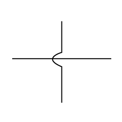
Represented by a small gap or semicircle at the intersection of two lines
Indicates that the pipes do not connect at the crossing point
Signal lines represent the communication pathways between instruments, control devices, and equipment. They are represented by various line types and symbols, including:
Pneumatic Signal
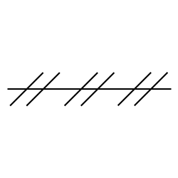
Represented by a dashed line
Uses compressed air to transmit signals
Guided Electromagnetic, Sonic, or Fiberoptic Signal

Represented by a dashed line with dots
Transmits signals using guided waves or light
Unguided Electromagnetic, Sonic, or Fiberoptic Signal

Represented by a zigzag line
Transmits signals through free space
Electric or Electronic Signal

Represented by a solid line with dots
Uses electrical or electronic signals for communication
Hydraulic Signal

Represented by a solid line with diamonds
Uses pressurized liquid to transmit signals
Various Data Communication Signals

Represented by a solid or dashed line with a specific symbol
Indicates the type of data communication used, such as digital or analog
Piping and Instrumentation Diagrams (P&IDs) provide a detailed visual representation of industrial systems.
Valve symbols are central to P&IDs. Each type of valve has a unique symbol reflecting its function:
Gate Valve: Controls full flow or shutoff.
Ball Valve: Allows quick on/off control.
Check Valve: Ensures one-way flow, preventing backflow.
Butterfly Valve: Compact for regulating or isolating flow.
Recognizing these symbols helps determine the purpose and role of valves in the system.
P&IDs illustrate the flow of materials through a system using lines and arrows. Key elements include:
Pipes: Show flow paths with arrows indicating direction.
Connections: Flanged, threaded, or welded, depending on system requirements.
Flow Indicators: Arrows and labels specifying media movement.
Properly interpreting flow paths ensures a clear understanding of system processes and dependencies.
Equipment symbols identify critical components like:
Pumps: Represented by circles or rectangles with markings for type.
Compressors: Indicated by symbols showing rotary or reciprocating motion.
Tanks and Vessels: Depicted as horizontal or vertical cylinders. Connections such as flanges, threaded joints, or welds are clearly labeled for easy recognition. Understanding these symbols simplifies system troubleshooting.
P&IDs serve multiple purposes:
Design: Engineers use P&IDs to create accurate blueprints for systems.
Operation: Operators monitor system performance and adjust processes as needed.
Maintenance: Technicians identify components and locate issues quickly.
Mastering valve symbols and P&ID is crucial for designing, operating, and maintaining industrial systems efficiently. It ensures clear communication across teams.
Effective use of P&IDs streamlines industrial processes. It improves safety, reduces downtime, and enhances system reliability for better productivity.
Engineers and operators benefit from continuous learning. Regular practice builds confidence in reading symbols and understanding complex diagrams.
Valve symbols and P&IDs form the foundation of industrial success. Embracing these tools is key to optimizing system performance.
RST Valve Group Co., Ltd., based in Wenzhou, China, boasts over 20 years of experience in industrial valve manufacturing, including ball, gate, check, and globe valves.


